Home
Antennas
Various
Attenuators
Broadband chokes
CW straight key selfmade
CW trainer
FT-991A output power
FT-991A cw envelope
Meter Nissei DG-503
> Resistive Bridge
Insulation Tester 6688B
Linear Supply PT110A
Impressum
Sitemap
Printable version
| An RF resistive bridge consists of just two 50 Ω resistors. It has one input E and two outputs A and B. | 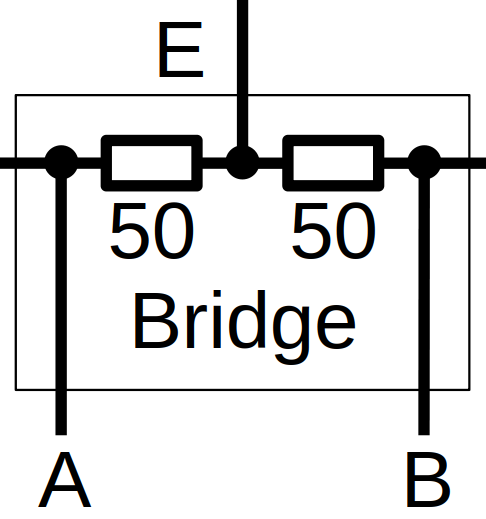 |
| RF is fed into input E, where a signal source TX with 50 Ω source impedance is connected. Port A is typically terminated with a reference load, e.g. a 50 Ω dummy load. Port B is connected to the unknown impedance. | 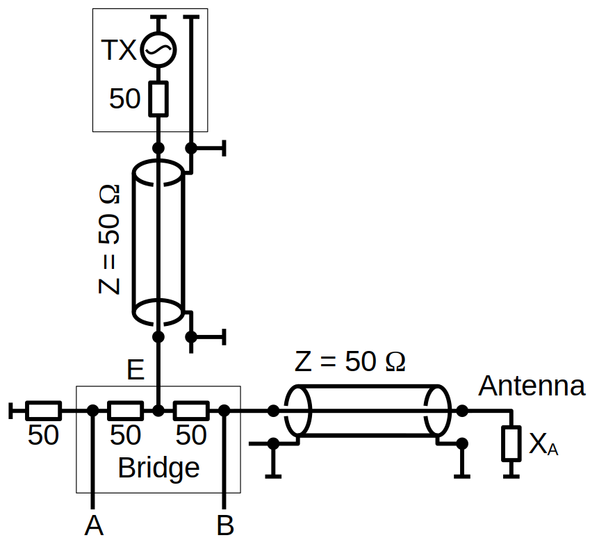 |
| Milling and drilling an aluminium block. | 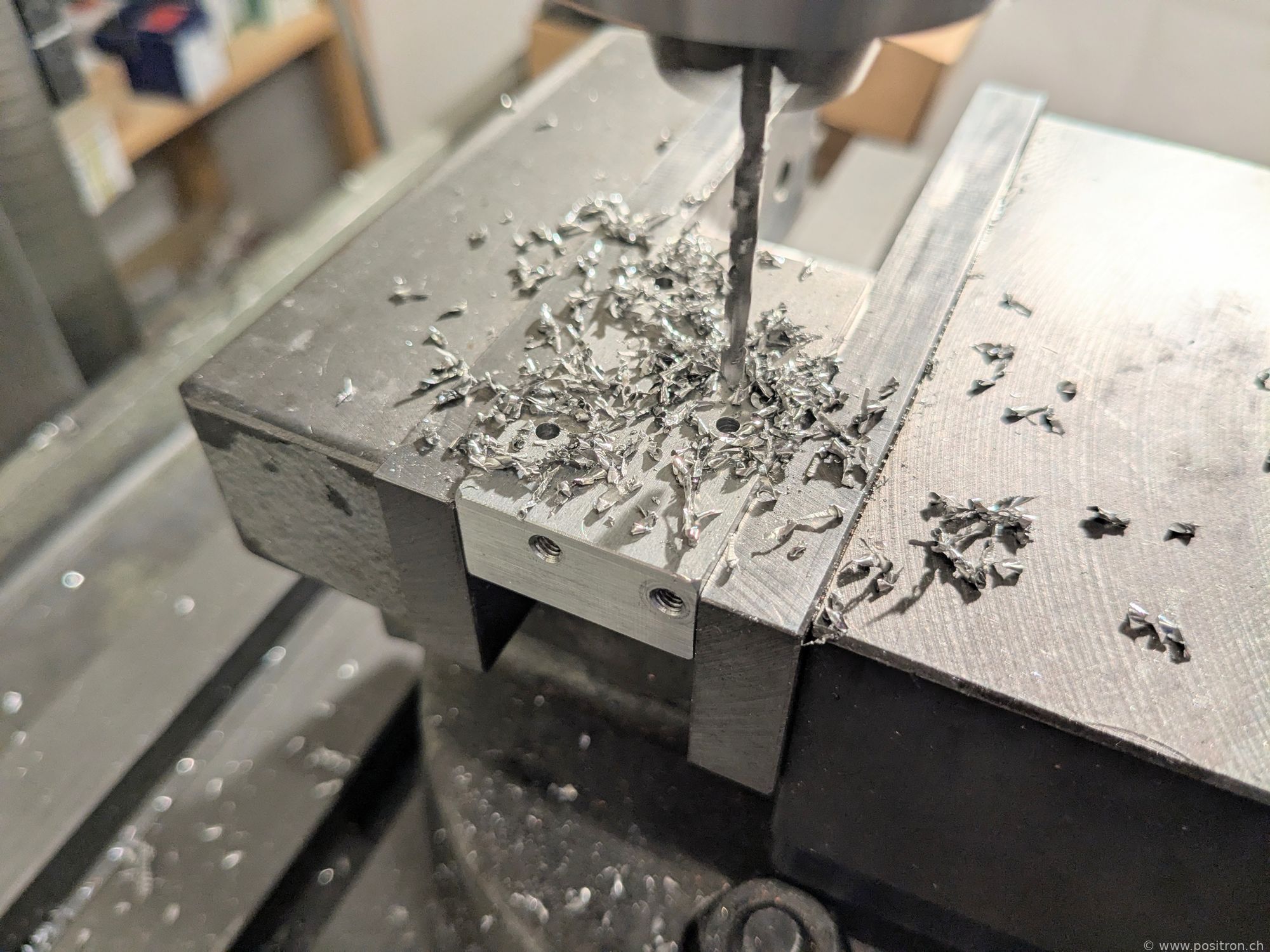 |
| Two resistors of type RFR 50-250: 50 Ω, 250 W each. Each bridge resistor is loaded with approximately one quarter of the input power. Theoretically up to around 1000 W could be fed into input E; I work with a maximum of 100 W. | 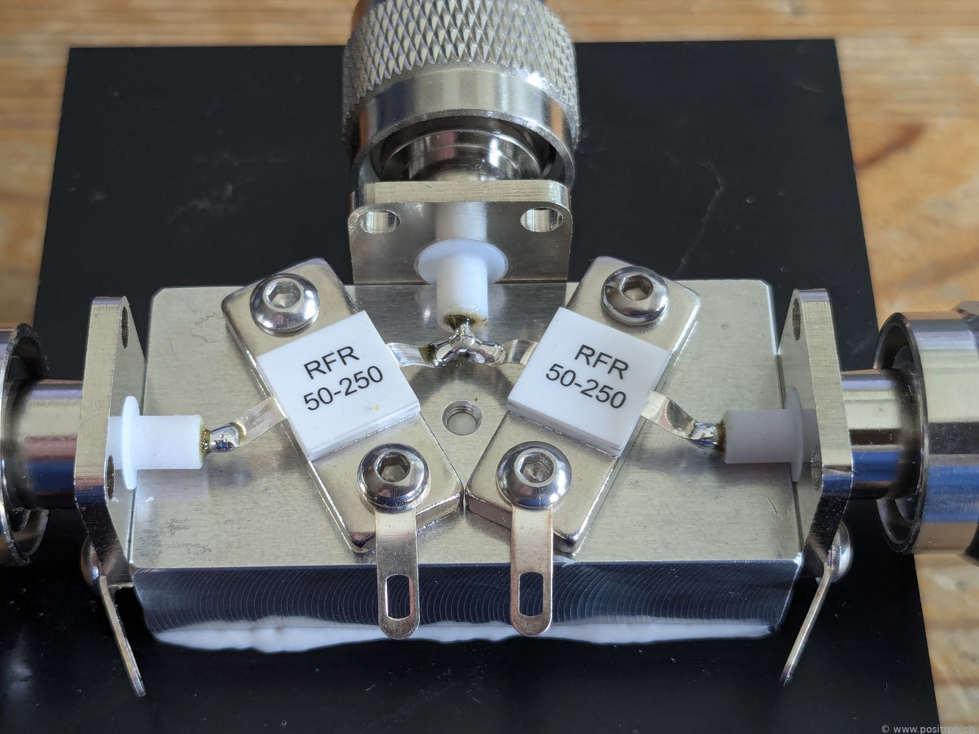 |
| A dummy load is connected to each of ports A and B to verify the symmetry of the bridge. | 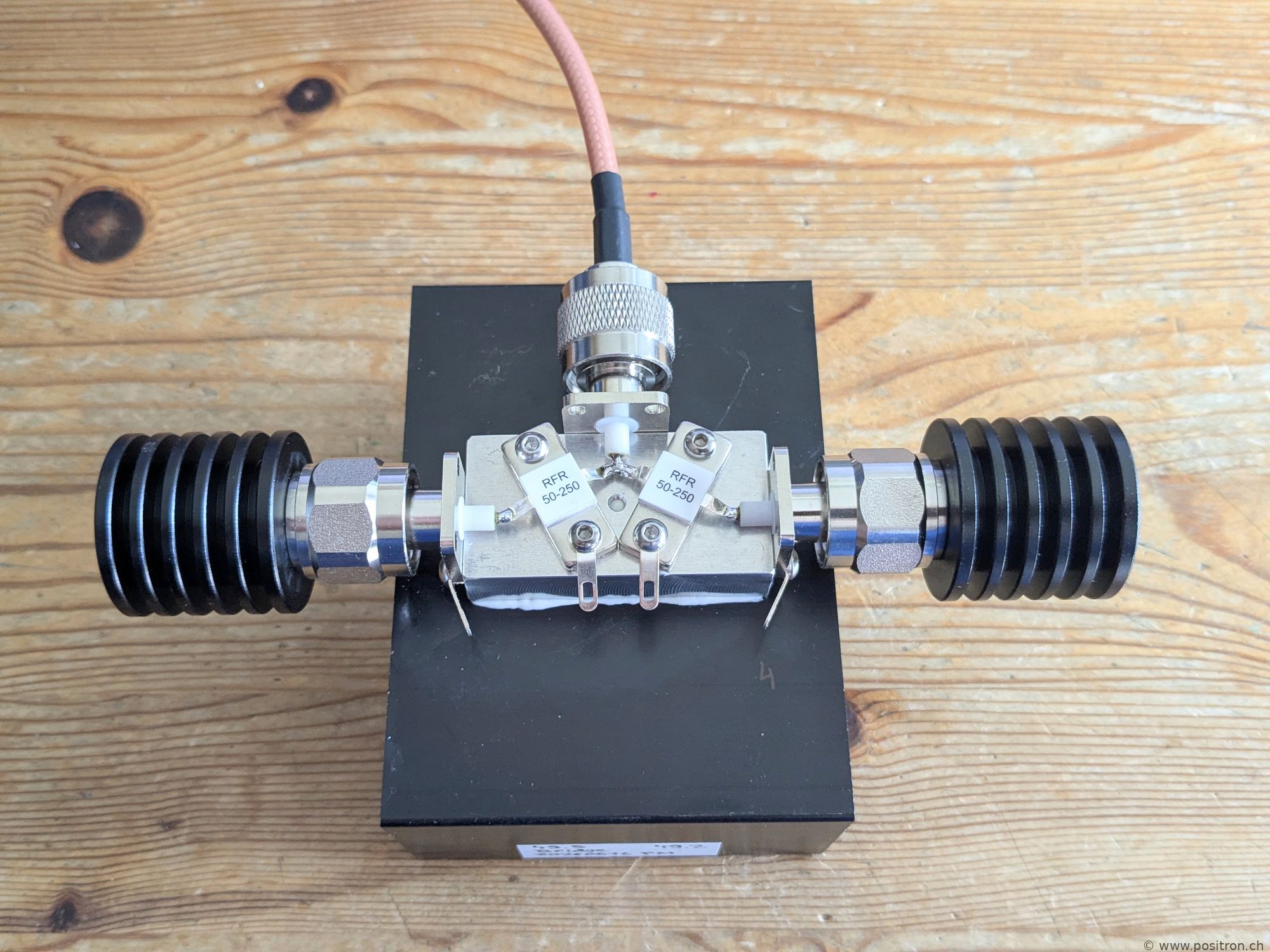 |
| Two oscilloscope probes are additionally connected to ports A and B. The probes are type P6100, inexpensive Chinese probes with approximately 10 MΩ and 20 pF input impedance. For a measurement at 1.8 MHz the capacitive reactance is about 4.4 kΩ, which has negligible loading effect on the 50 Ω bridge. | 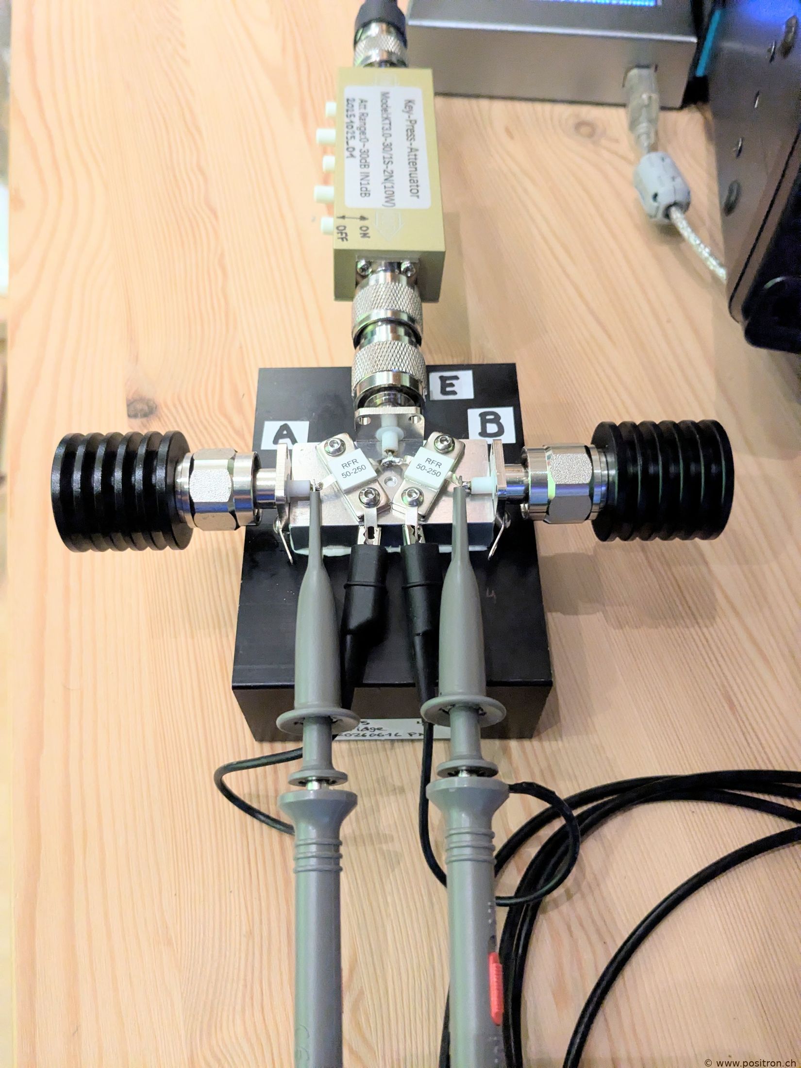 |
| Measurement is done with a Digilent AD3. Together with the 1:10 probes, up to 250 Vp can be measured, which is more than sufficient. The power at input E is adjustable: 5 to 100 W from the transmitter, a fixed 30 dB attenuator, and a variable 0 to 31 dB attenuator in 1 dB steps. This gives a range from 100 W down to 4 µW (+50 dBm to −24 dBm) in 1 dB steps. | 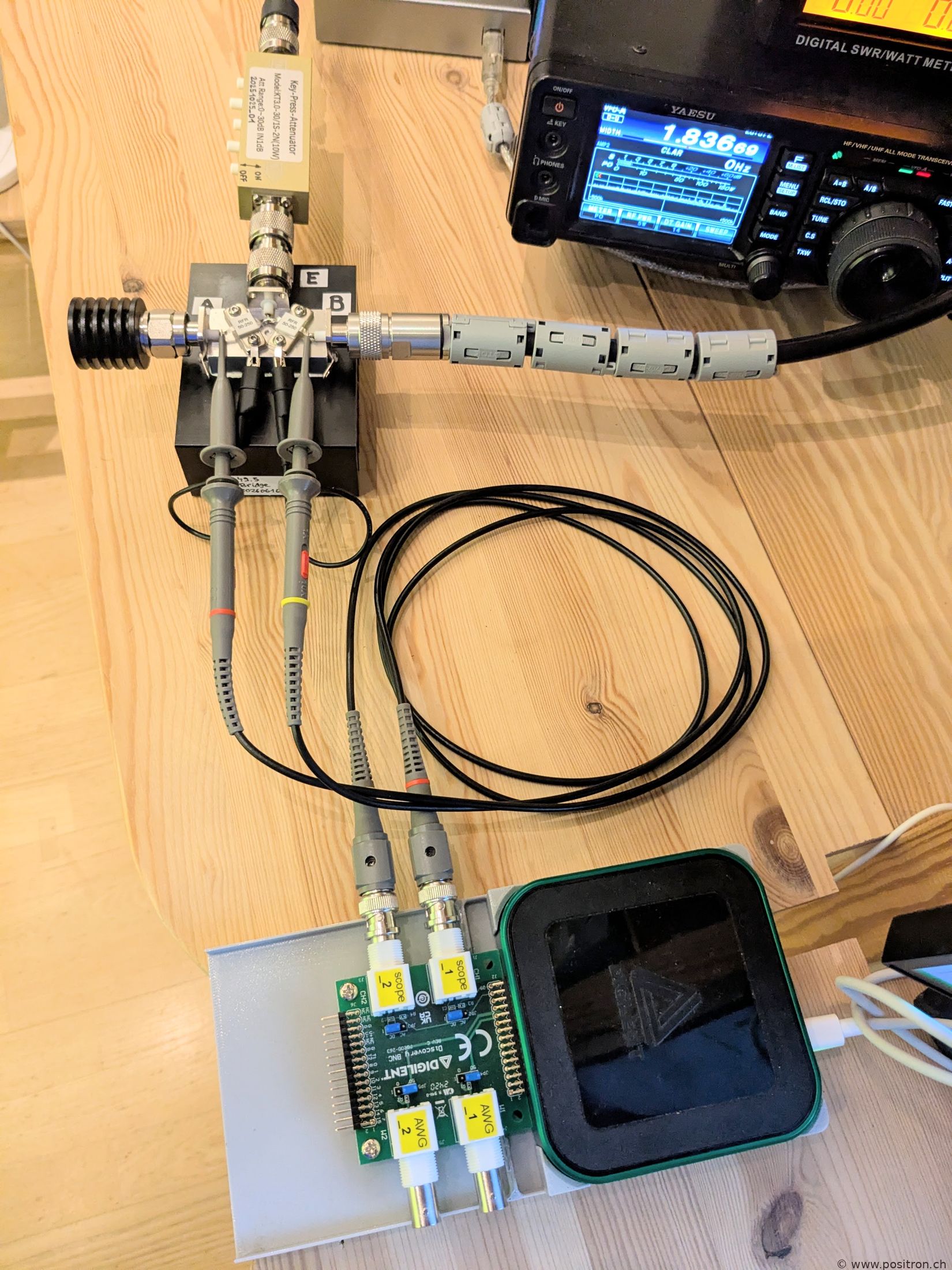 |
Theory: Antenna Impedance from Bridge Voltages
The resistive bridge is driven by a source E with 50 Ω internal impedance. The two bridge resistors are each 50 Ω. Port A is terminated with a 50 Ω reference load; port B is connected to the unknown antenna impedance ZA.
The bridge equations are:
- A = E / 2 (A is the reference voltage at port A)
- B = E · ZA / (50 + ZA) (B is the voltage at port B)
With E = 2A the antenna impedance follows directly:
ZA = 50 · B / (2A − B)
In the general (complex) case, A is taken as the phase reference (phase = 0°), so A = a (real). Channel B is measured with amplitude b and phase difference φ, giving the complex voltage B = b · (cosφ + j sinφ). Substituting:
ZA = 50 · b ejφ / (2a − b ejφ)
This yields both the resistive part R and the reactive part X of the antenna impedance ZA = R + jX, which can be plotted directly on a Smith chart. The reflection coefficient and SWR are:
Γ = (B − A) / A SWR = (1 + |Γ|) / (1 − |Γ|)
If no phase measurement is available, only the RMS amplitudes a = |A| and b = |B| are known. In that case φ is unknown and only |Γ| can be determined:
|Γ| = |b − a| / a
This gives the SWR but not the full impedance ZA.