Home
Antennas
Various
Attenuators
Broadband chokes
CW straight key selfmade
CW trainer
FT-991A output power
FT-991A cw envelope
> Meter Nissei DG-503
Resistive Bridge
Insulation Tester 6688B
Linear Supply PT110A
Impressum
Sitemap
Printable version
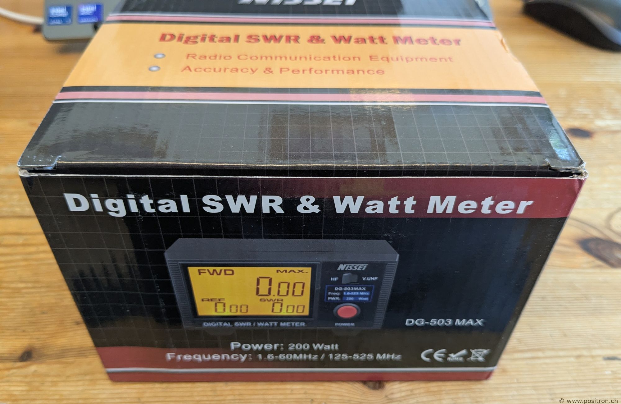
Nissei DG-503 SWR & Wattmeter
I bought an SWR meter and am writing a short review here. Upfront: do not buy!
For about 160 USD including shipping from China. I assume I did not buy a fake device — I found no signs indicating it is not an original.
|
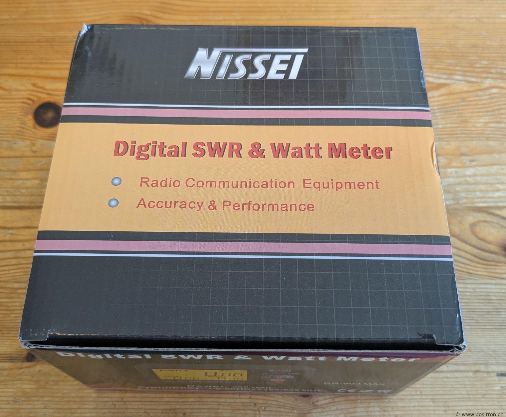
Cardboard box with nostalgic-looking colors. |
 |
 |
|
|
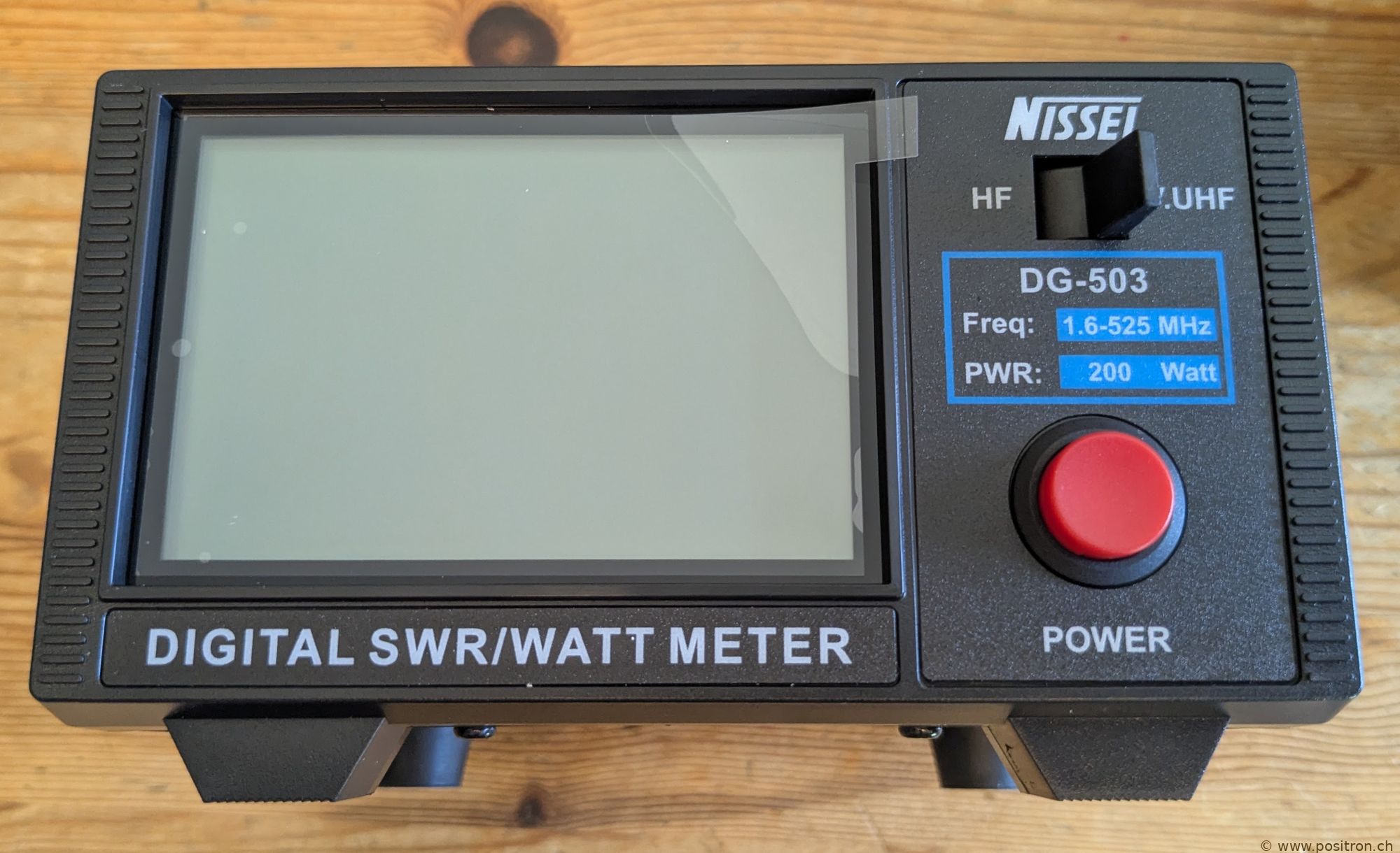
Front view. |
 |
|
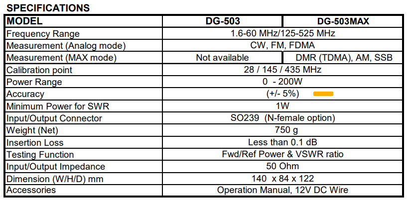
The specification is not very informative. Perhaps that is why the author put the ±5% in parentheses — as if to say "wishful thinking" or "marketing goal, not a guarantee". |
 |
|
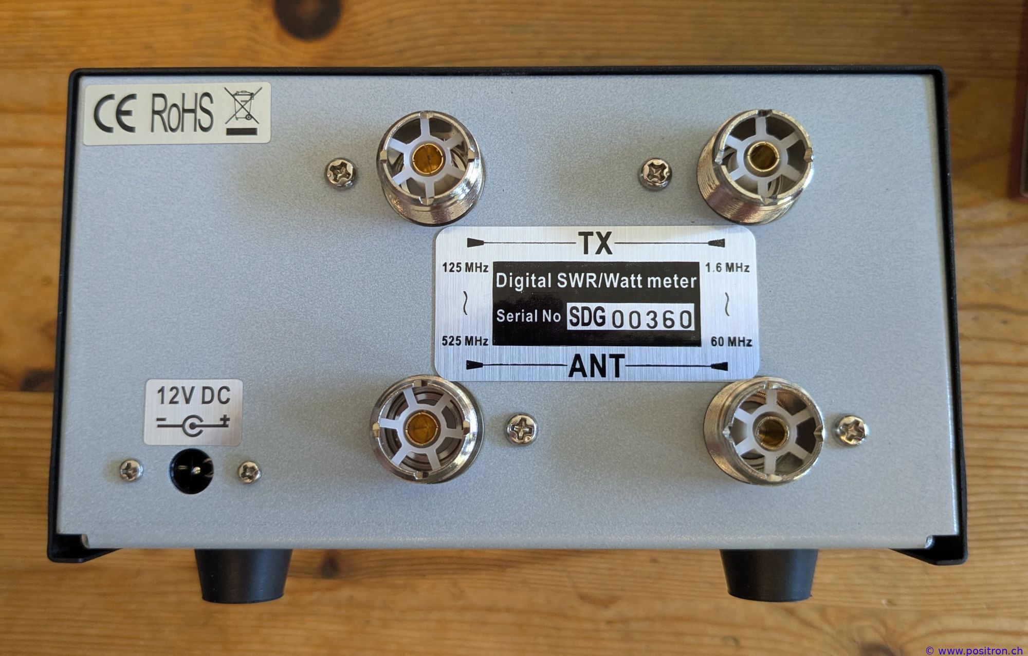
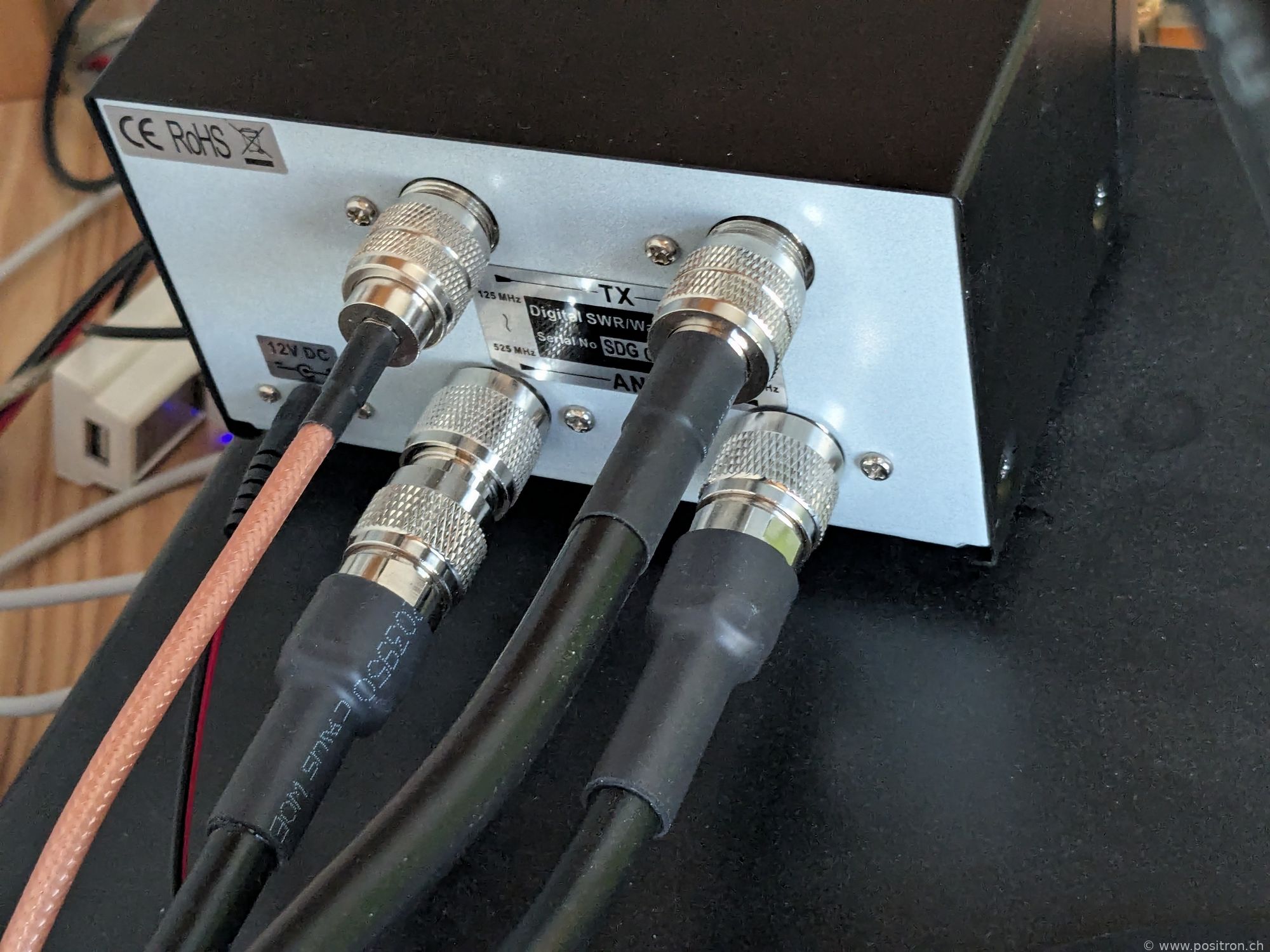
Rear view. It is a pity that no Type N connectors are used. Especially at higher frequencies the SO-239 connectors are already at a disadvantage. |
 |
|
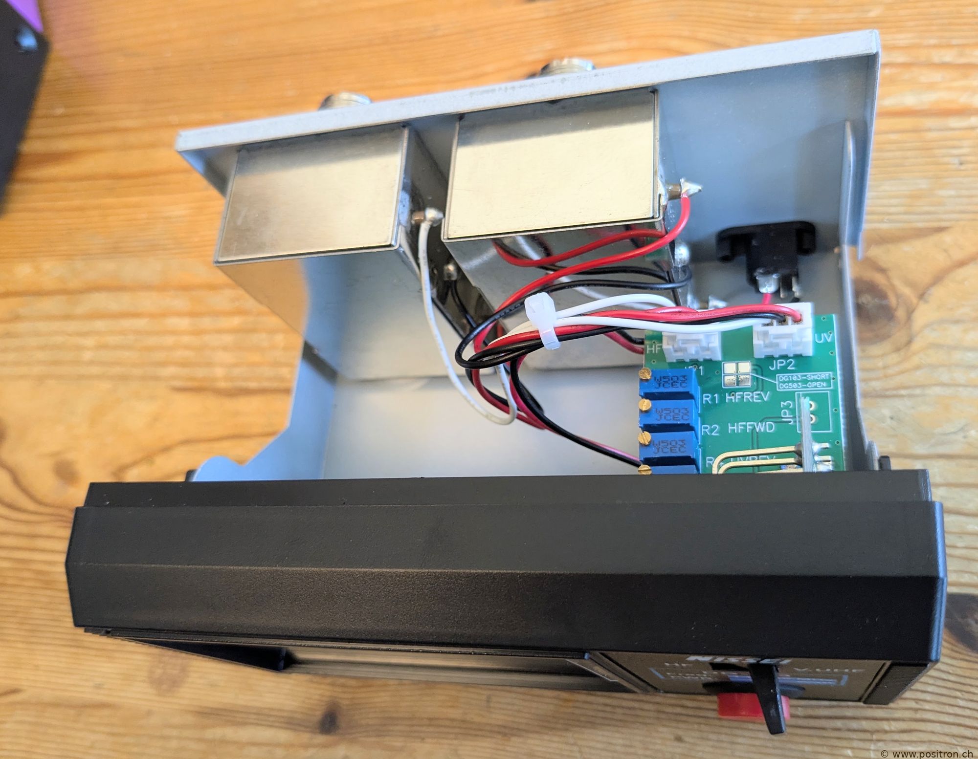
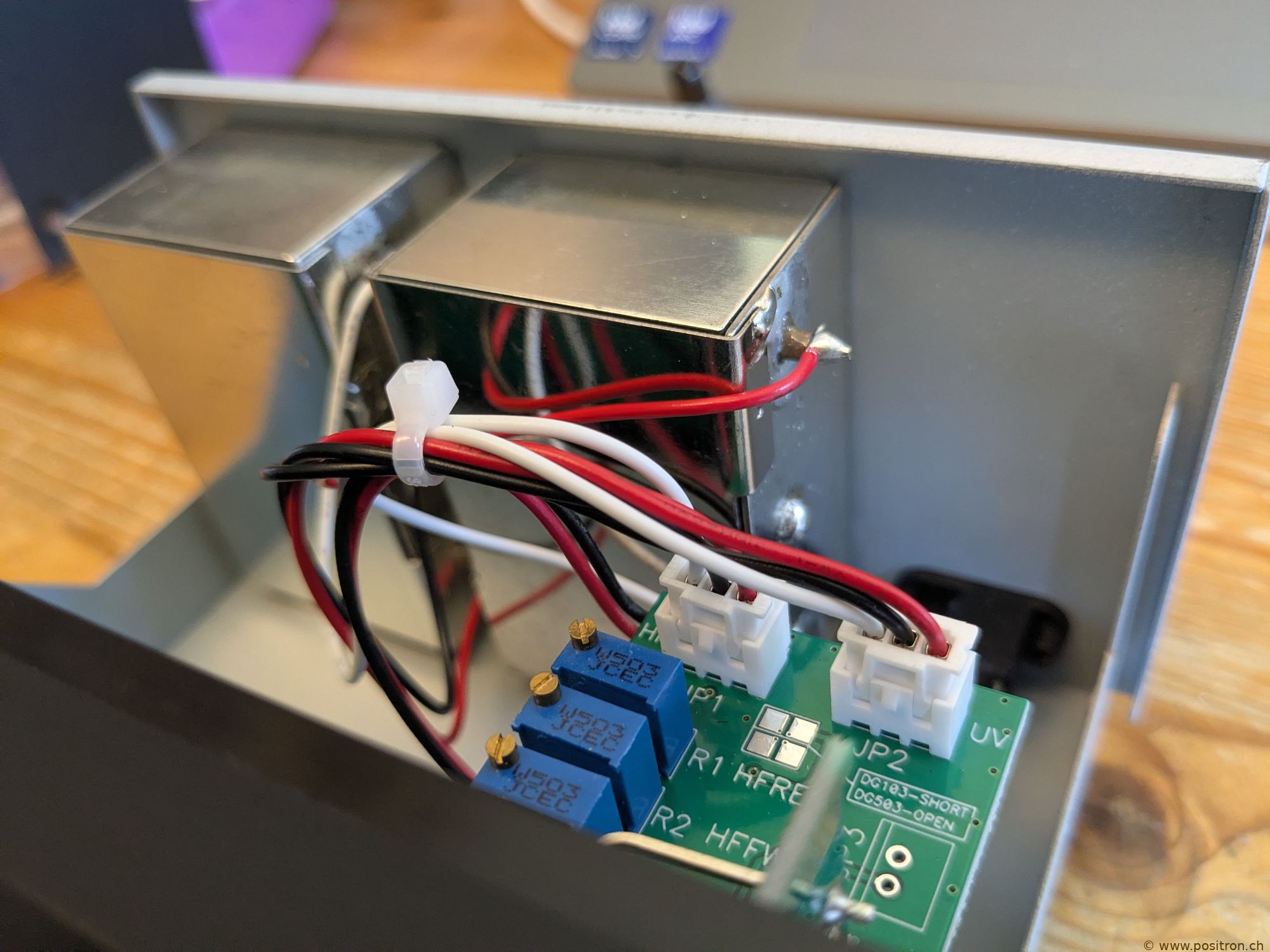
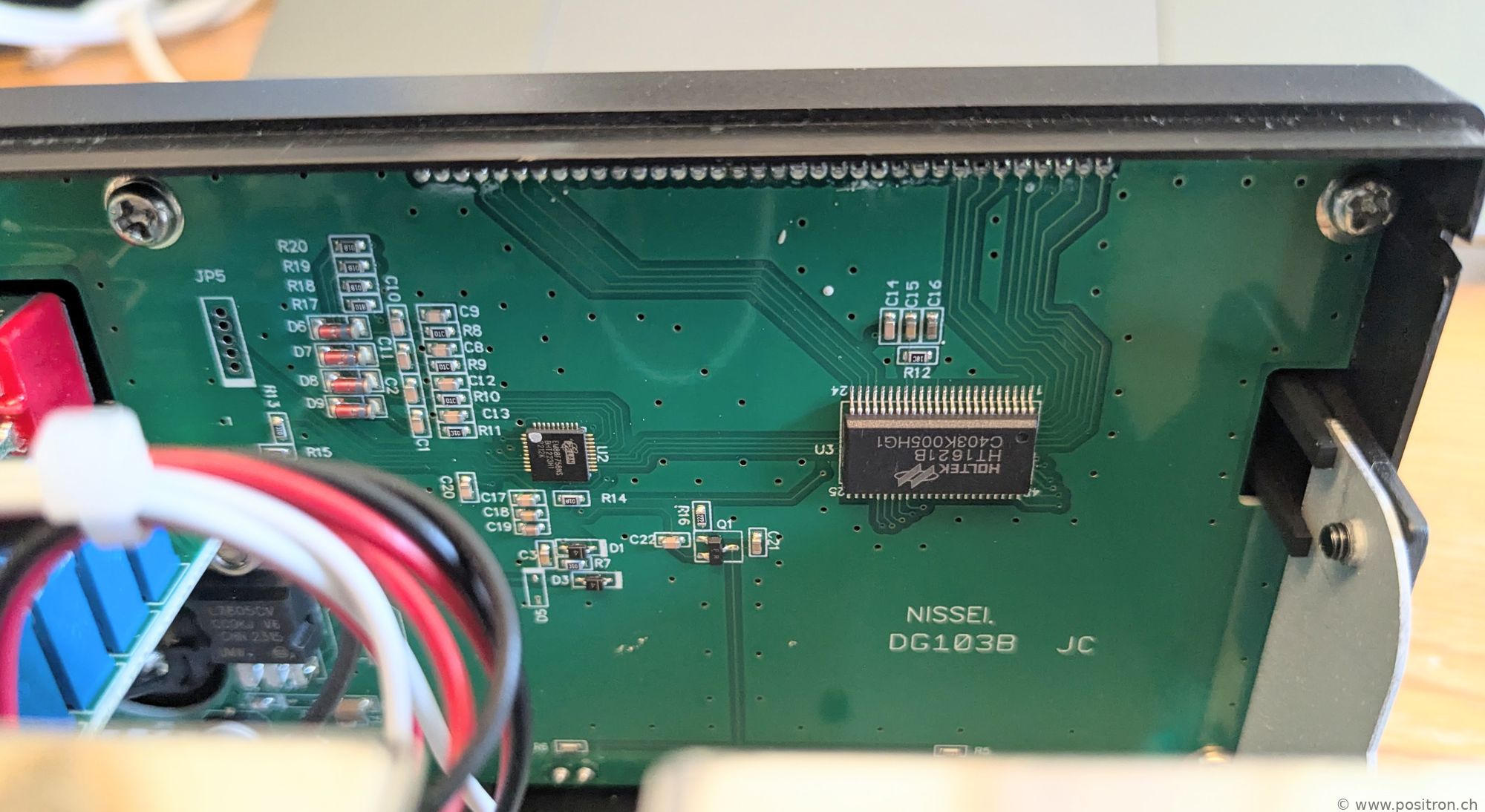
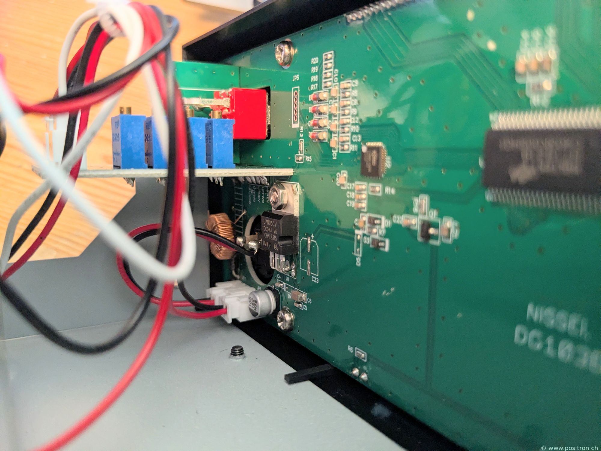
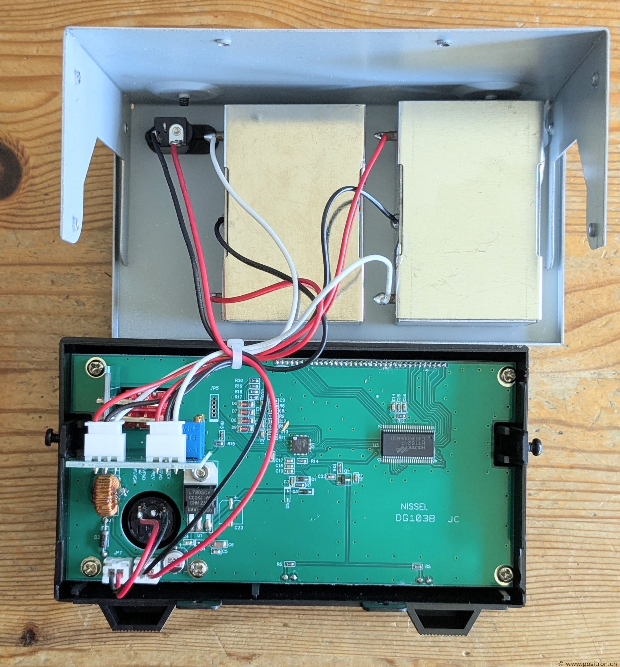
View of the interior. Two separate directional couplers in a metal enclosure. |
 |
 |
|
|
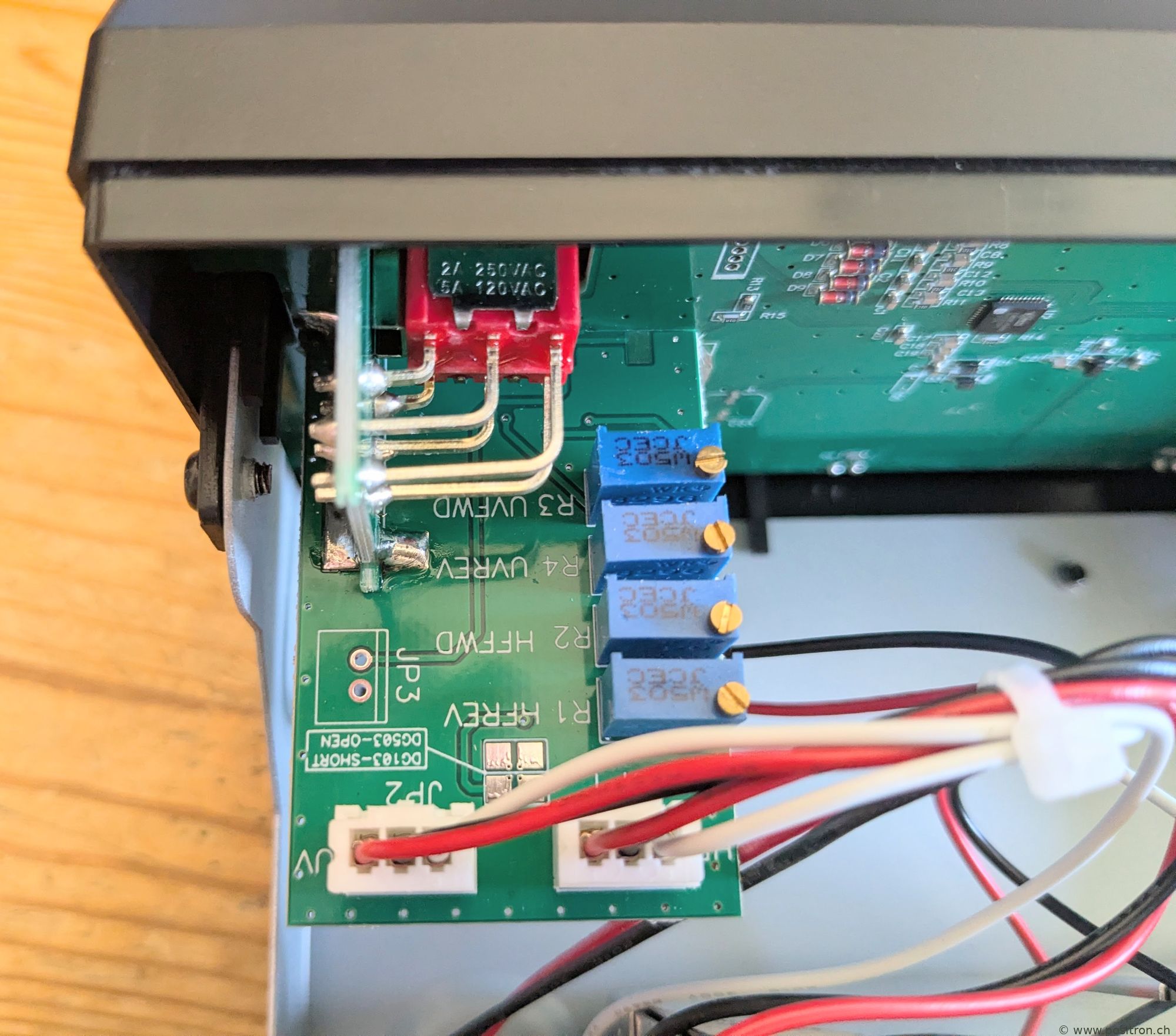
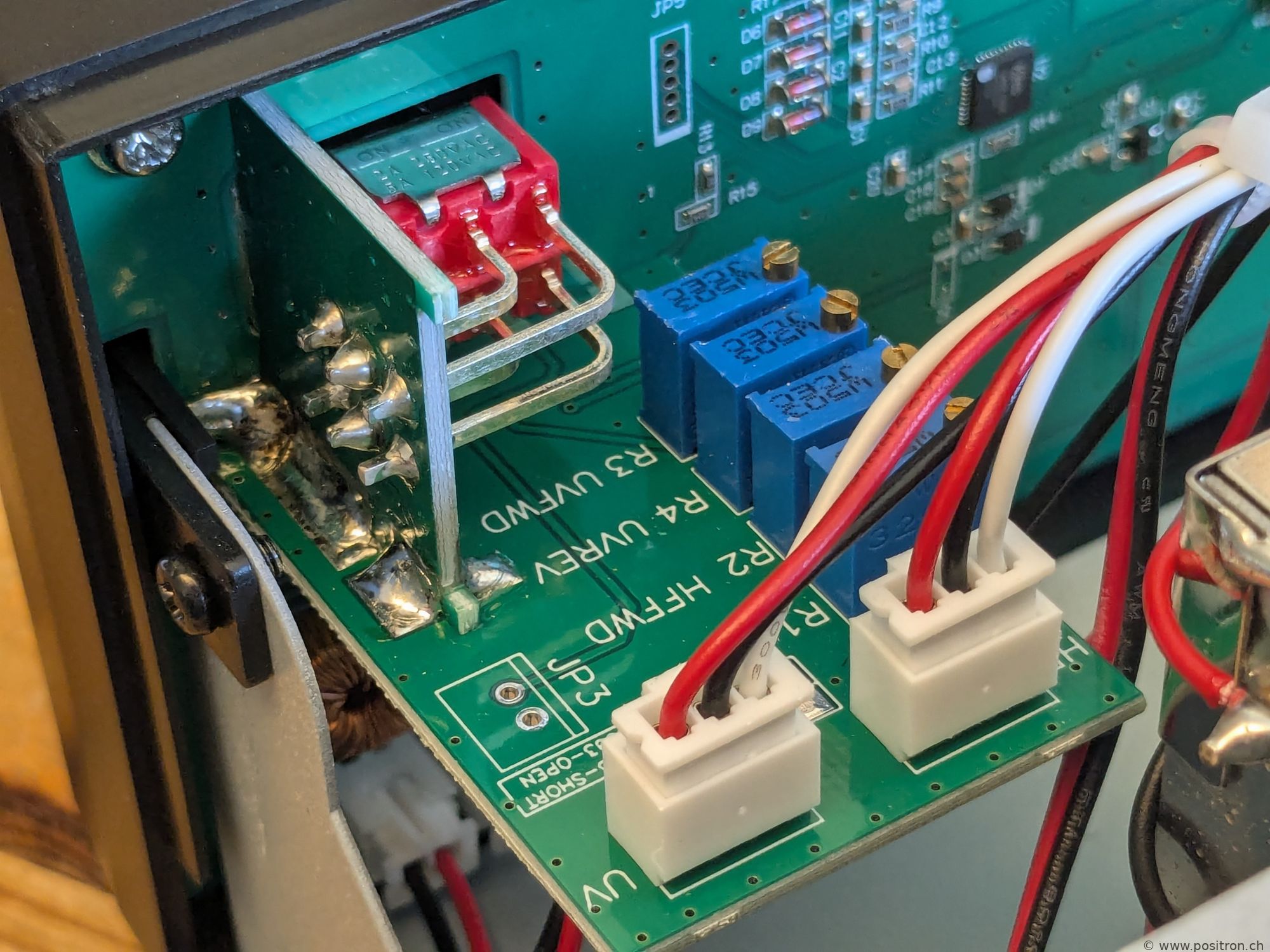
4 trimmers. This is apparently the only adjustment available to the manufacturer. Remarkable. |
 |
 |
|
 |
|
 |
|
|
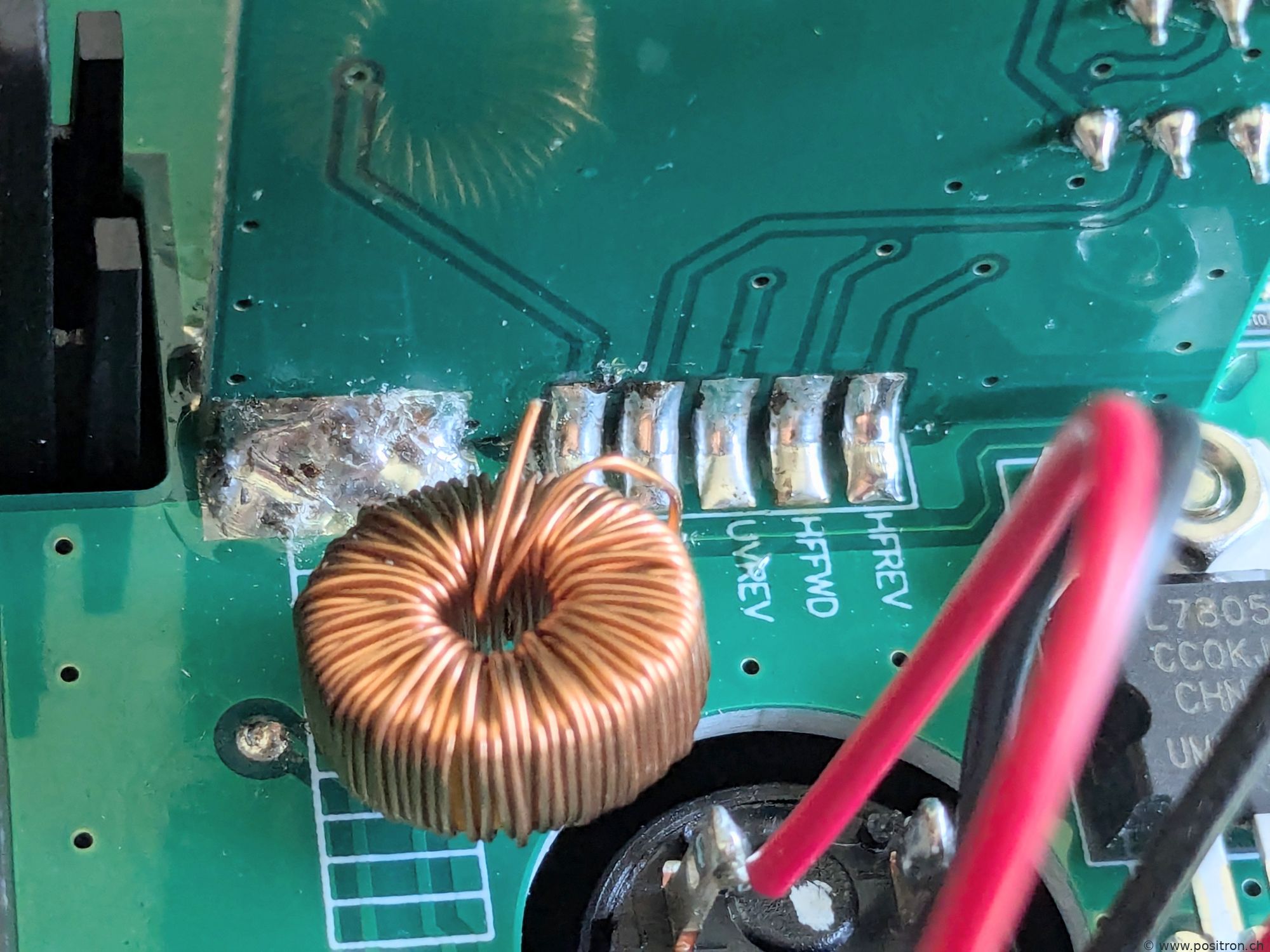
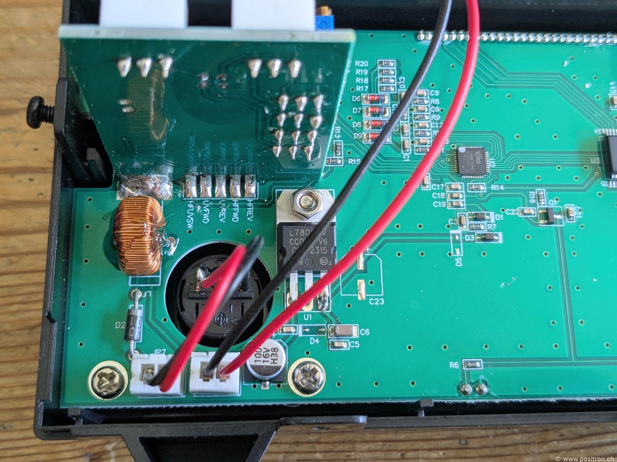
This coil broke off during shipping. It was not mechanically secured and simply hung on the thin wires. Poor quality. |
 |
 |
|
|
Coil re-soldered by me and mechanically secured with adhesive. |
 |
 |
|
|
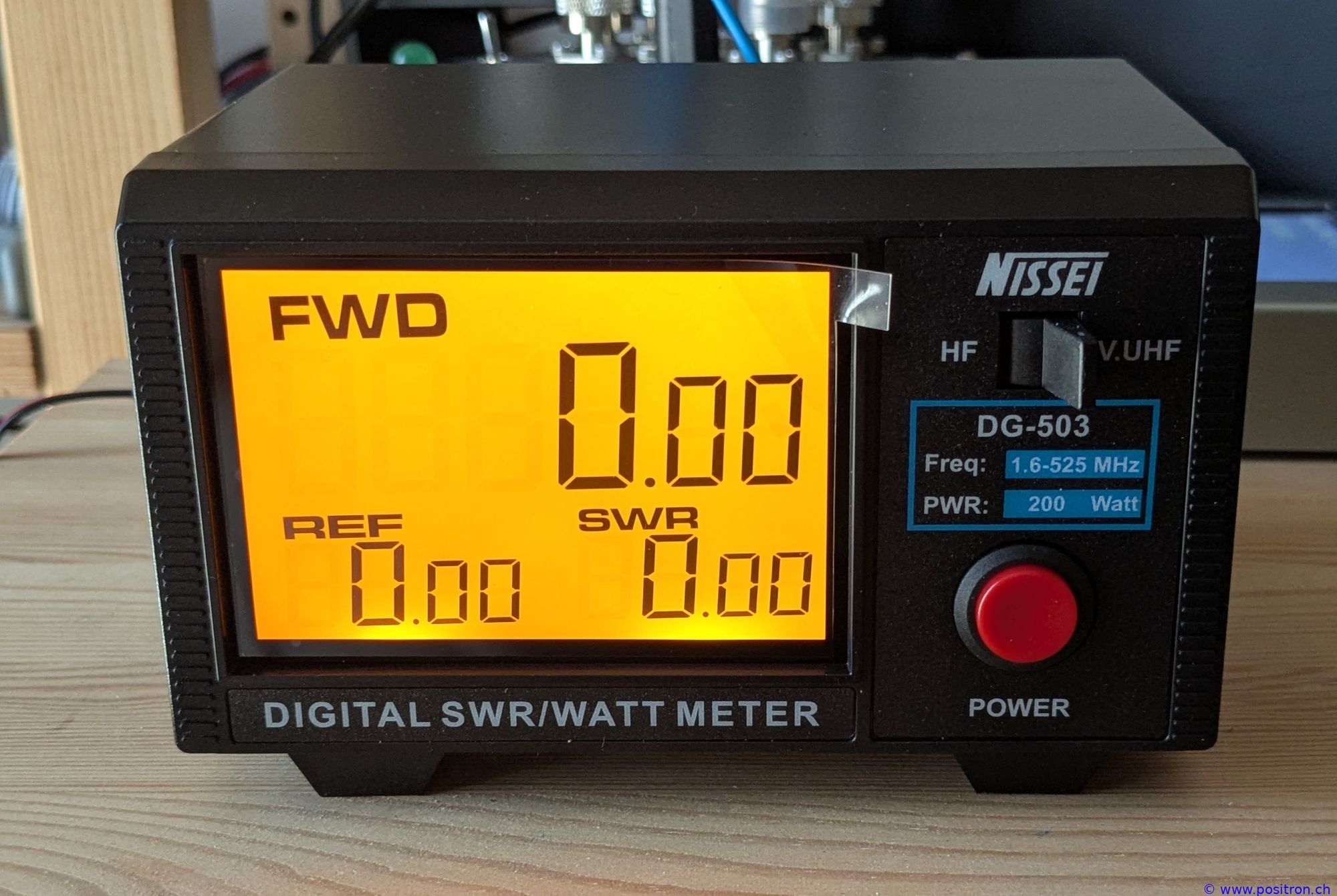
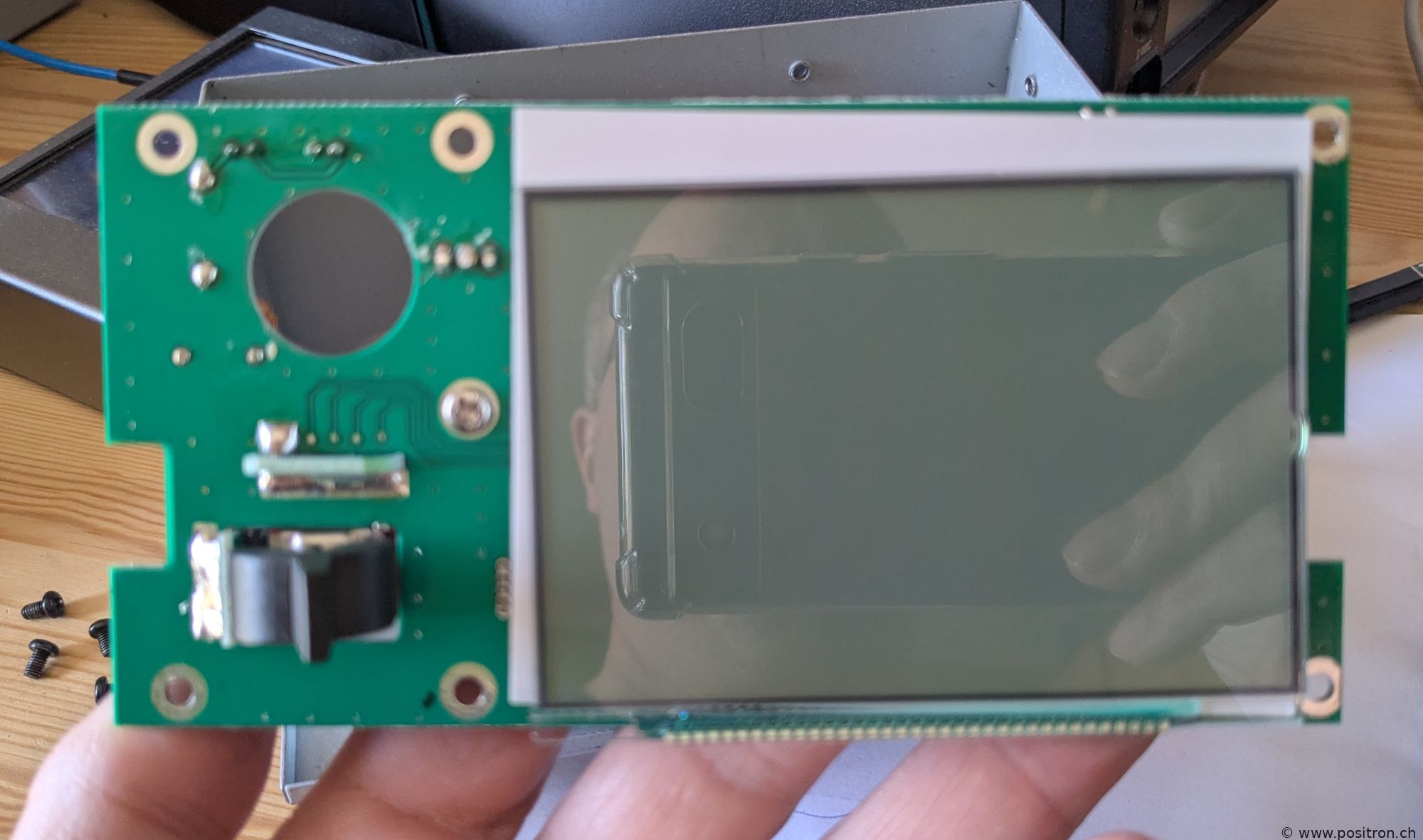
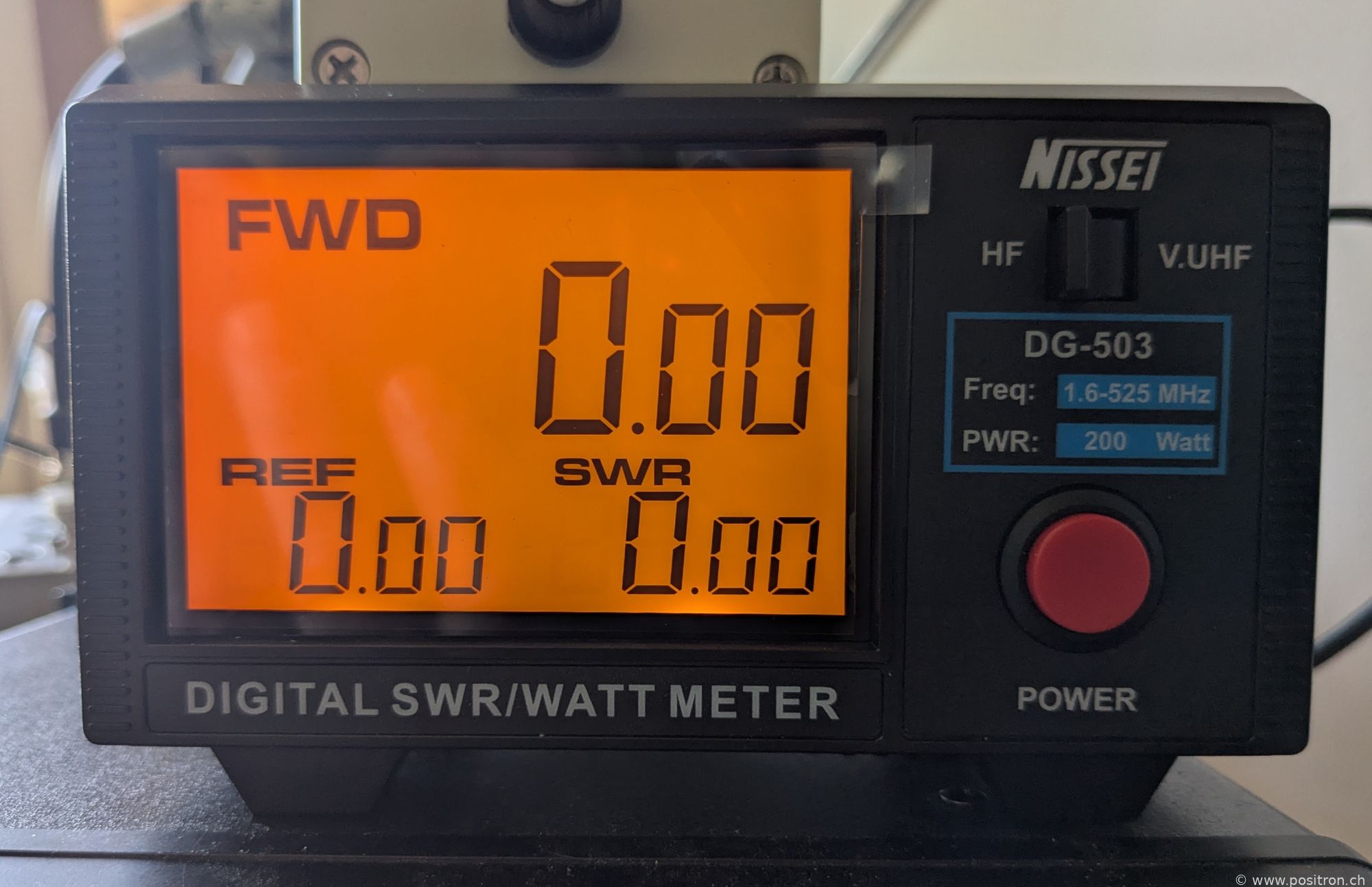
Lights up nicely, large digits. If you look closely you can see: the display is mounted slightly crooked. |
 |
|
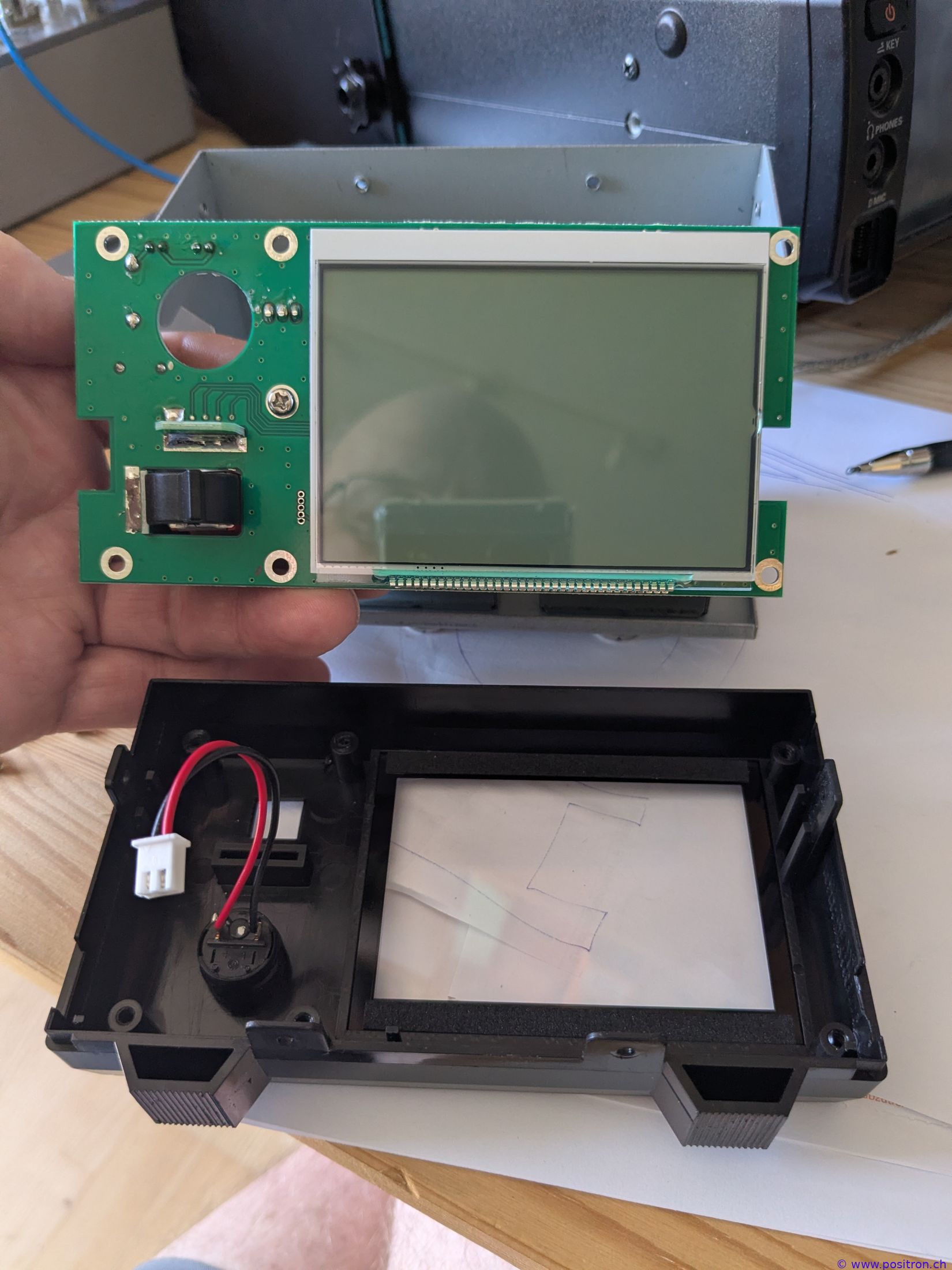
I disassemble the device — yes, the display connectors are severely bent. |
 |
|
I bend it into the correct position. |
 |
|
Now it is aligned with the housing. |
 |
|
Cable plugged into the Nissei. |
 |
|
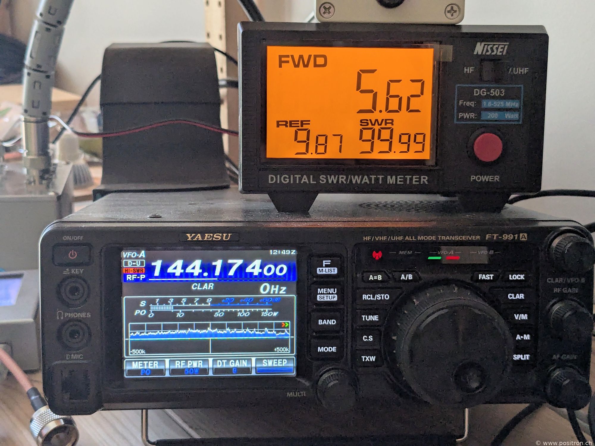
SWR meter on top of the transceiver. Anyone looking at the numbers will quickly notice: things are about to get interesting. |
 |
|
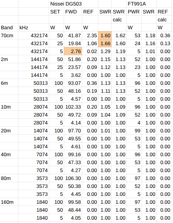
The FT991A also displays power and SWR. However, the measurement built into the transceiver is said to be not very accurate, so I hope to get more precise readings with the external Nissei. First test: I connect the outputs of the FT991A to the SWR meter and then to a 50 ohm dummy load (JFW 50FA0-030-100, 100W 0 to 3 GHz). I set the power on the FT991A, measure FWD, REF and SWR with the DG503. I then calculate the SWR from FWD and REF, which should match the displayed SWR. I read the FT991 via rigctl and get PWR and SWR from it. Based on these values I calculate the reflected power from REF. At higher frequencies the SWR and the rather low FWD power surprise me. I suspect the power is displayed too low and the SWR too high. Matched load, low SWR: a standard case, the readings are not particularly remarkable. |
 |
|
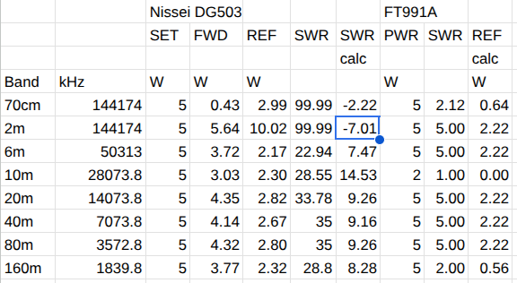
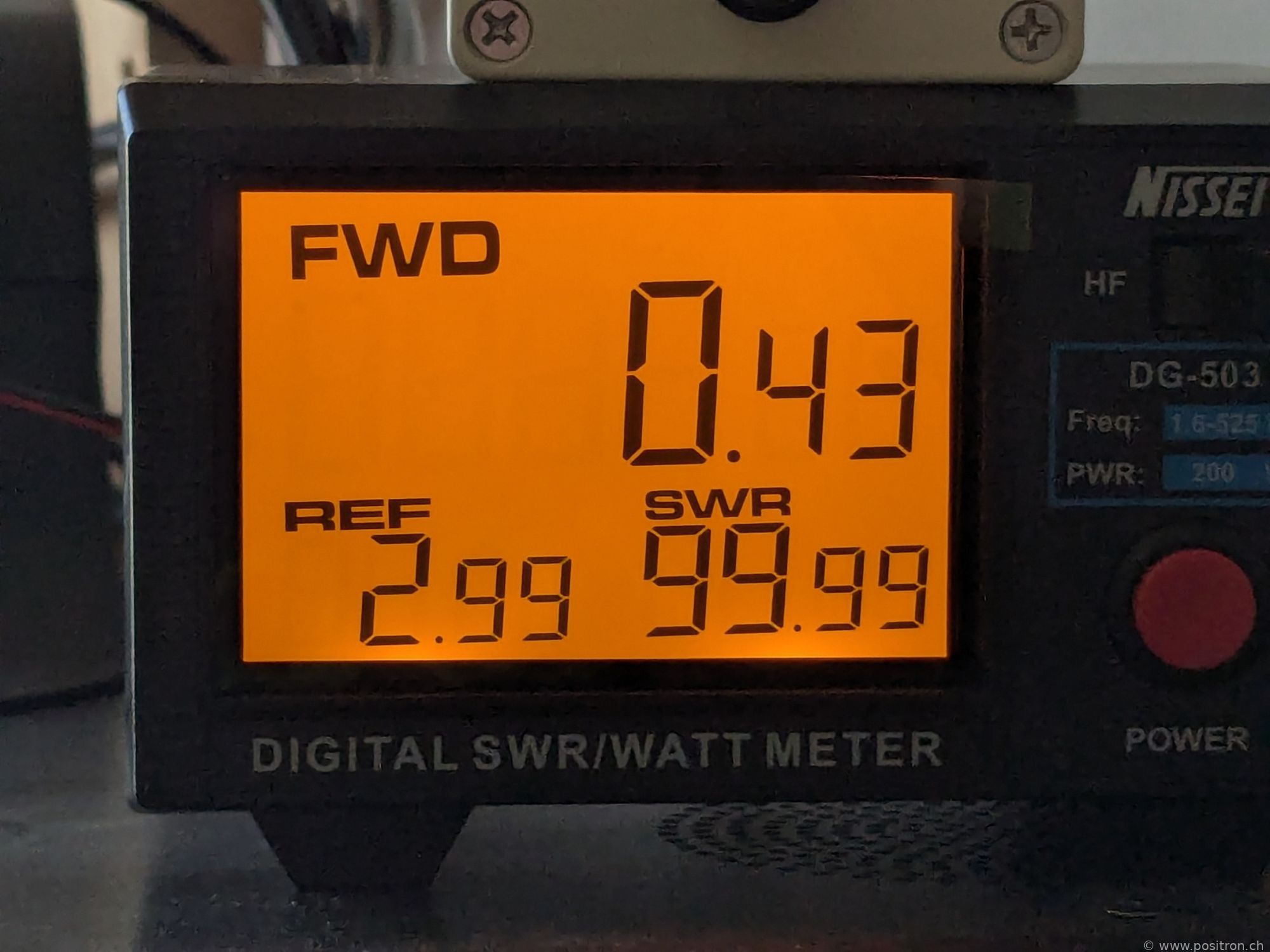
I disconnect the load directly at the Nissei and leave the connector open. I expect 100% reflection, i.e. FWD = REF and an SWR of infinity. The displayed values are quite bizarre. When the reflected power is several times larger than the forward power, something is seriously wrong. The FT991A also shows interesting values — it seems to never display an SWR above 5. |
 |
|
Hard to believe what it says. |
 |
|
Now with a short circuit. 0 ohm, I expect 100% reflection, i.e. FWD = REF and an SWR of infinity. The FT991A limits output power to protect its PA, down to about 10 W. Here too, the values are bizarre. |
 |
|
I connect two 50 ohm resistors in parallel, giving 25 ohm. |
 |
|
At the low frequencies shown in this measurement, these are certainly perfect 25 ohm. |
 |
|
I expect REF to be 11% of FWD, and the SWR should be 2. The 25 ohm load gives Γ = (50−25)/(50+25) = 1/3, so PREF/PFWD = (1/3)² ≈ 11%, and SWR = (1+1/3)/(1−1/3) = 2. I cannot go above 20 W to avoid overloading the resistors. |
 |
|
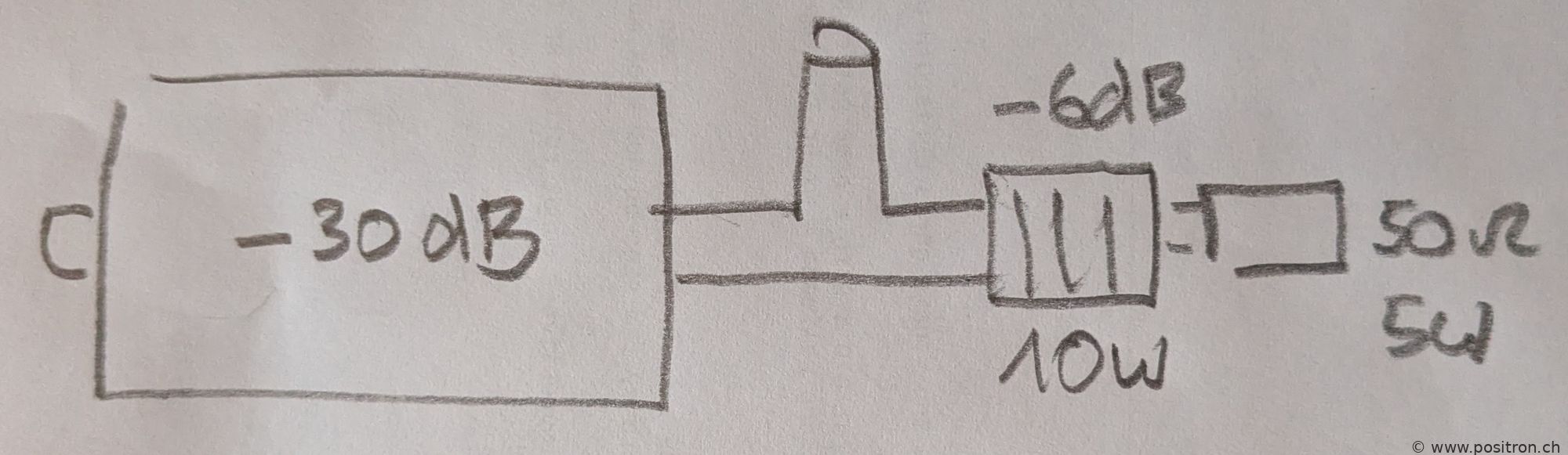
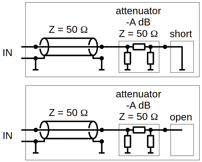
After all these results, I do another measurement round. I use a key-press attenuator to generate various loads and thus various reflection coefficients. Key-Press-Attenuator KT3.0-30/1S-2N (10 W, in dB steps from 0 dB to 31 dB attenuation). The attenuator is terminated with either a short circuit or an open circuit, allowing various reflection coefficients to be achieved. |
 |
|
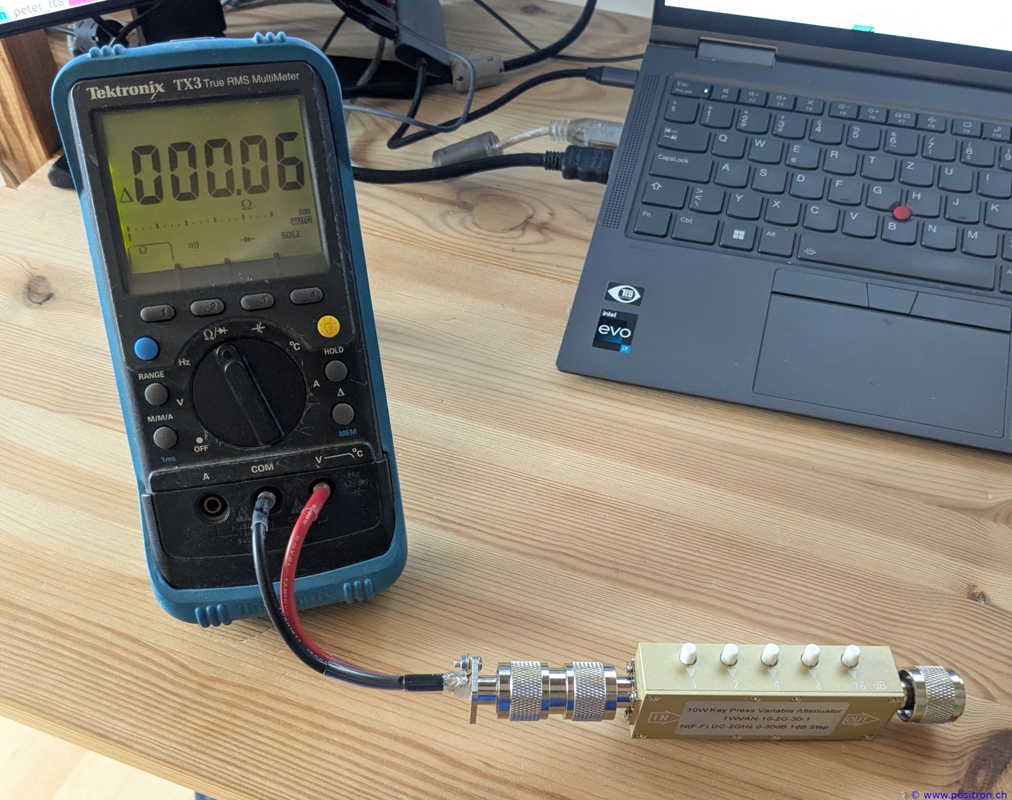
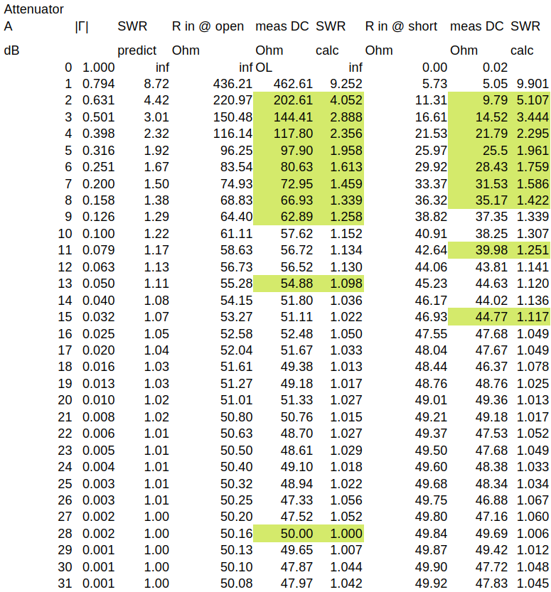
I set all possible attenuation combinations, terminate with a short or open, and measure the DC resistance. I estimate the error of my DC resistance measurement to be less than 0.1 ohm. From the DC resistance I calculate the expected SWR. I select 19 different combinations, yielding 15 defined SWR values. |
 |
|
DC resistance measurements. Highlighted in green are the combinations used for the following measurements. |
 |
|
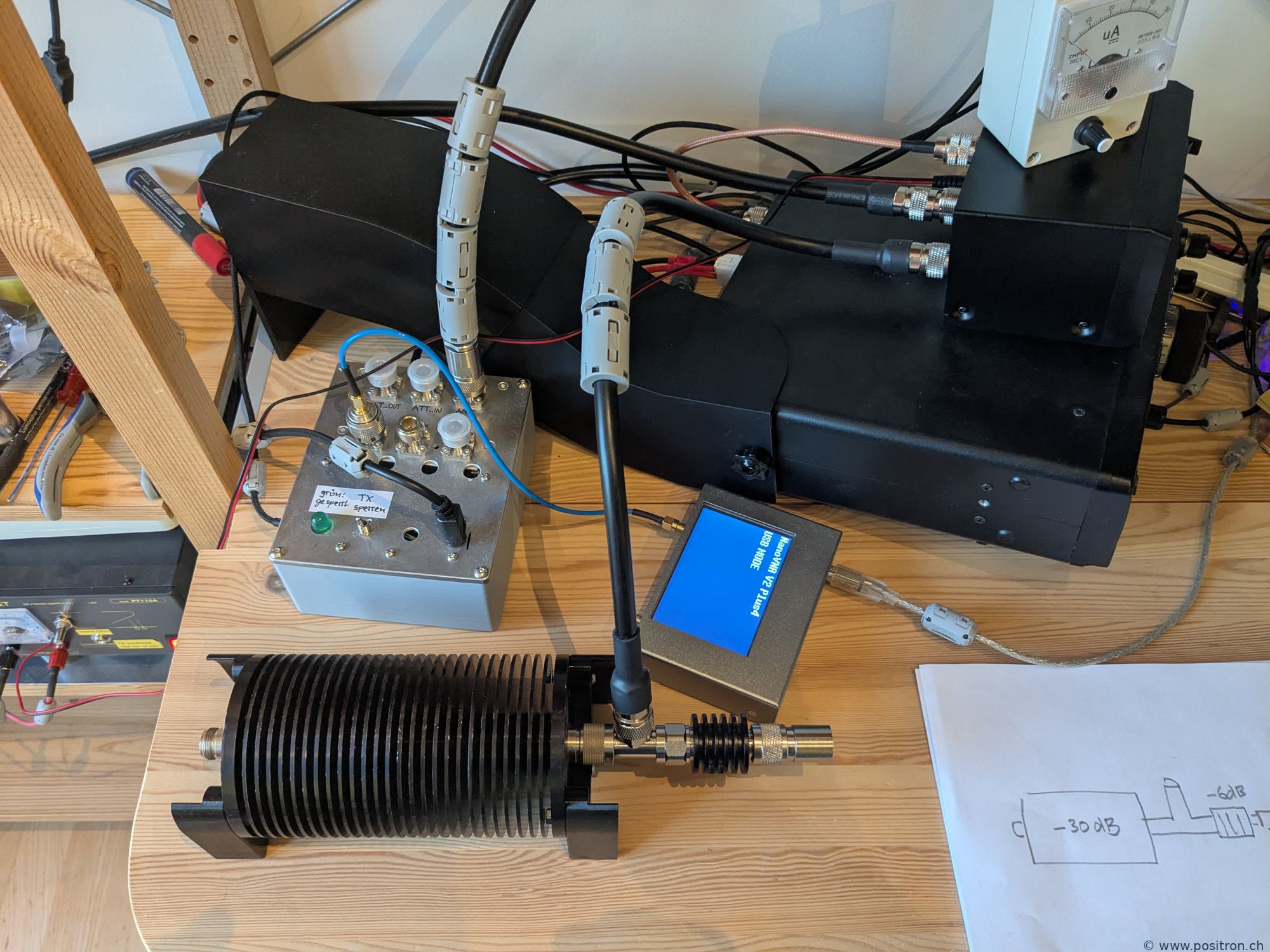
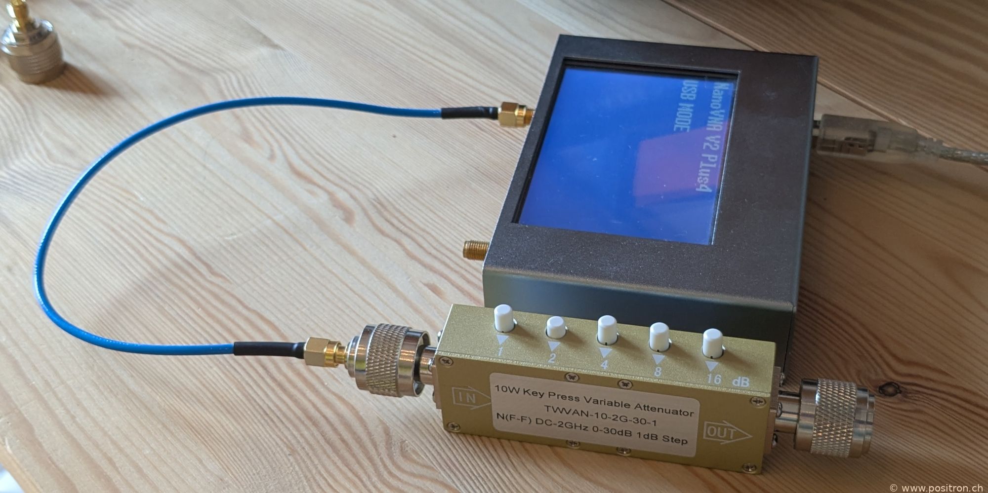
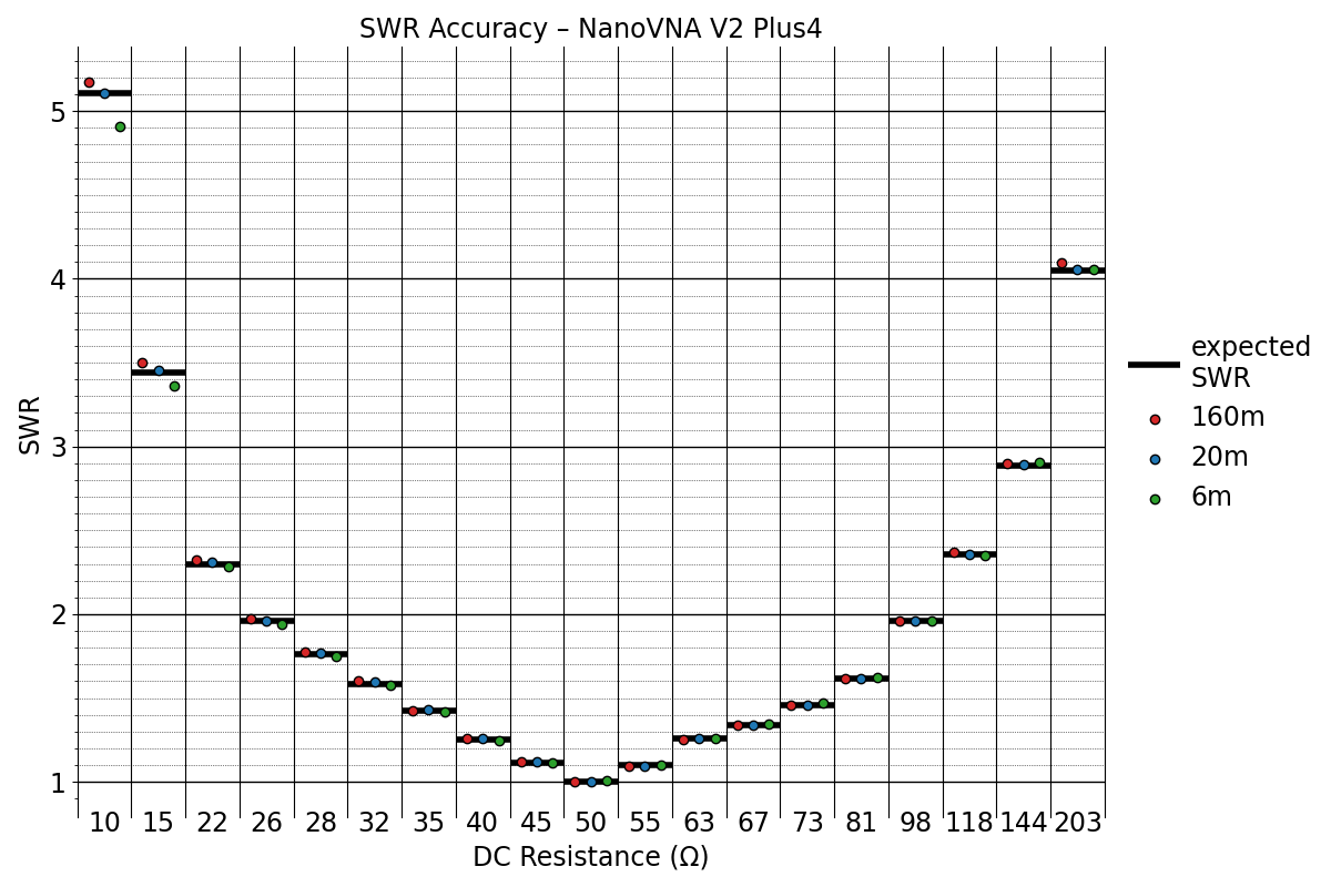
I calibrate my NanoVNA V2 Plus4 at the end of the blue cable, then connect the attenuator (shown here with a short at the end). |
 |
|
SWR values measured with the VNA. The results match very closely the expected SWR calculated from the DC resistance measurements (shown as "expected SWR" in the diagram on the right). |
 |
|
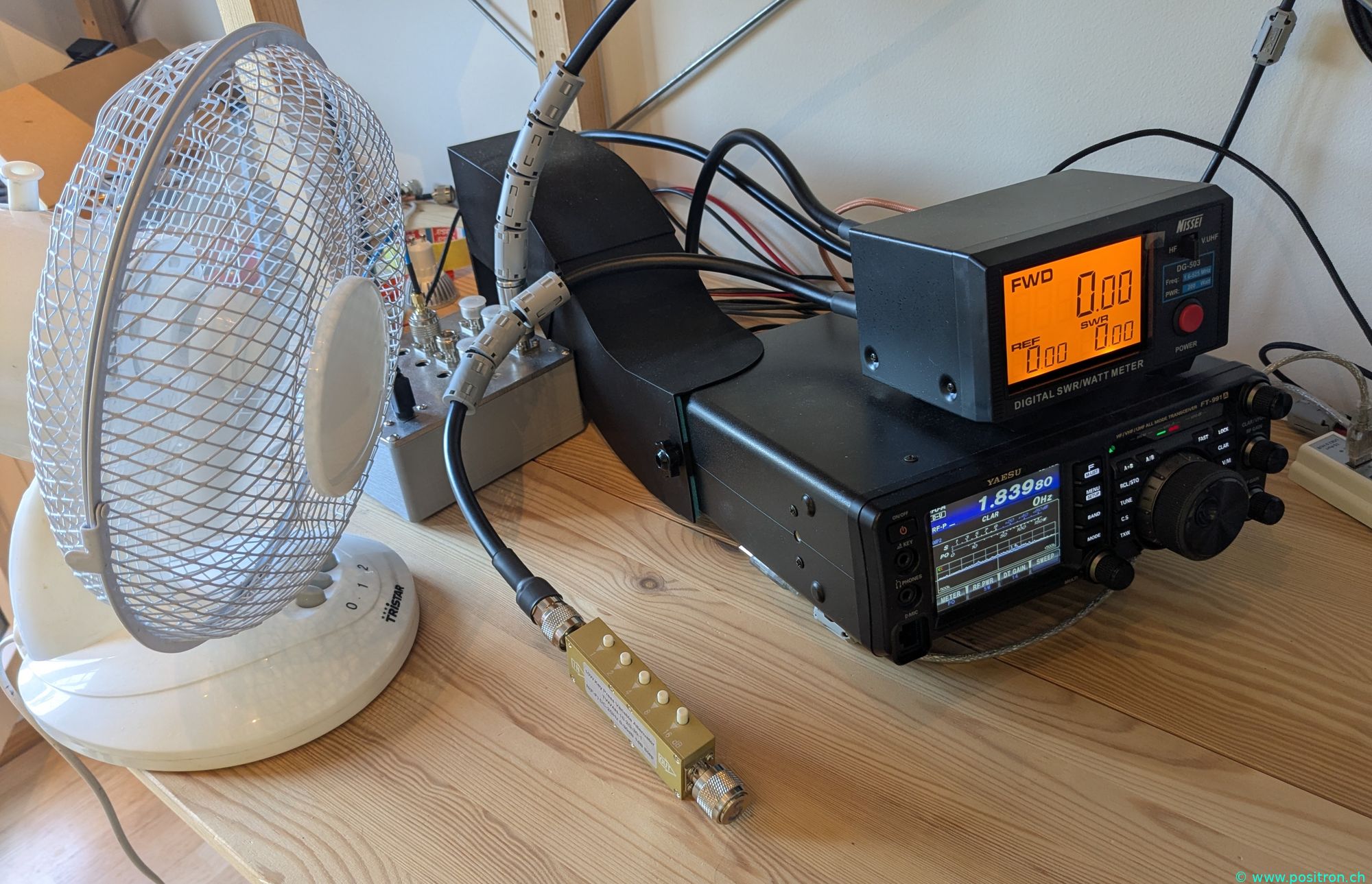
I now connect my known termination to the Nissei / FT991A. The termination can handle up to 10 W. A fan is used for cooling; between measurements I let the resistors cool down. |
 |
|
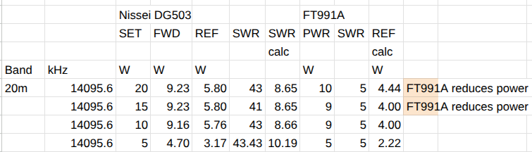
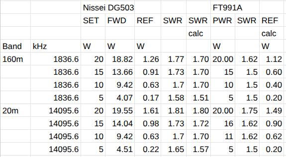
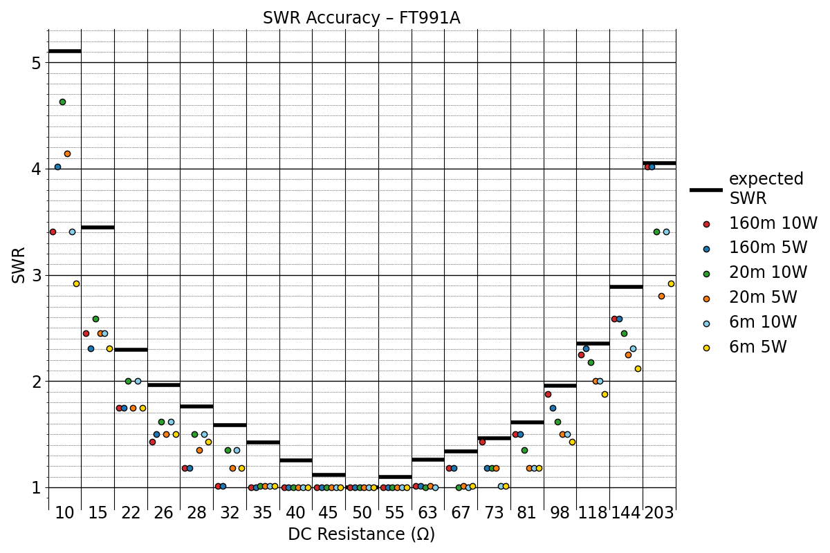
Readings from the FT991A. The displayed SWR is always too low. The FT991A does not market itself as an SWR meter — it likely just includes a basic measurement circuit to protect its output stage. In that sense, fair enough. |
 |
|
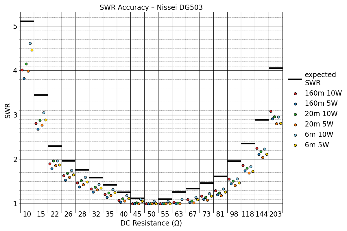
Readings from the Nissei. The displayed SWR is also always too low. Disappointing. |
 |
|
Systematically displaying SWR values that are too low helps to conceal errors. The user sees a low SWR and is pleased. If a falsely high SWR were shown instead, the user would try tuning the antenna, never manage to bring the SWR down to 1.0, and sooner or later replace the meter with a different one. |
|
Background: FWD, REF and SWR
Here is the relationship between the power values FWD, REF and SWR:
- Reflection coefficient: Γ = (ZL − Z0) / (ZL + Z0)
- Reflection coefficient from power: Γ = √(PREF / PFWD)
- SWR = (1 + Γ) / (1 − Γ)
- Combined: SWR = (1 + √(PREF/PFWD)) / (1 − √(PREF/PFWD))
- Inverse: PREF/PFWD = ((SWR − 1) / (SWR + 1))2
Note: PREF can never exceed PFWD. A ratio above 1 is physically impossible and indicates a faulty instrument.
Conclusion
I am disappointed. In my opinion the Nissei DG503 is quite unusable as a measurement instrument.
With severe mismatch, the displayed readings are extremely inaccurate. With moderate mismatch, the SWR values are systematically too low.
The three values FWD, REF and SWR displayed by the Nissei are not consistent with each other — the relationship between them does not follow standard calculation methods.
Adding a Nissei DG503 alongside an FT991A makes little sense — the accuracy is not meaningfully better.