Home
Antennas
Various
Attenuators
> Broadband chokes
CW straight key selfmade
CW trainer
FT-991A output power
FT-991A cw envelope
Meter Nissei DG-503
Resistive Bridge
Insulation Tester 6688B
Linear Supply PT110A
Impressum
Sitemap
Printable version
Broadband Chokes
I need chokes for both coaxial lines and mains power lines. Buy or build? Build!
For my magnetic loop antenna, which covers 160 m through 10 m, I need chokes that work across a wide frequency range. I was inspired by several people, for example F5NPV's CMC page with a compilation by G3TXQ.
I chose a series combination of recommended toroid configurations:
- Low frequencies – 17 turns on 2 stacked FT240-31 toroids (Fair-Rite 2631828302)
- Mid frequencies – 9 turns on 4 stacked FT240-43 toroids (Fair-Rite 5943003801)
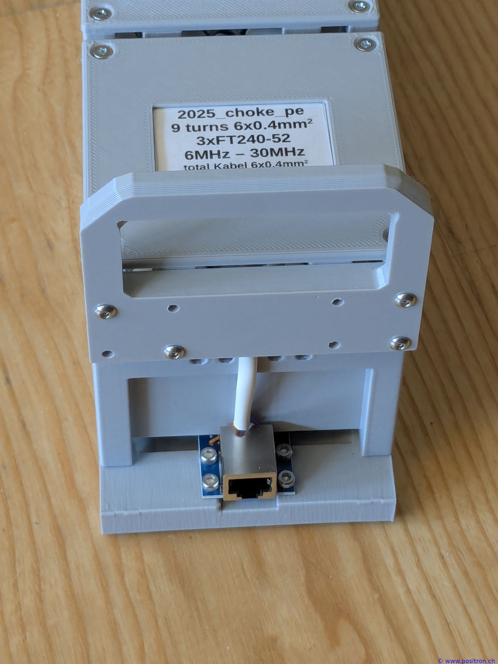
- High frequencies – 9 turns on 3 stacked FT240-52 toroids (Fair-Rite 5952003821)
Optimization goals:
- Low capacitance to the toroid – maintain some spacing
- Low turn-to-turn capacitance – controlled spacing between windings
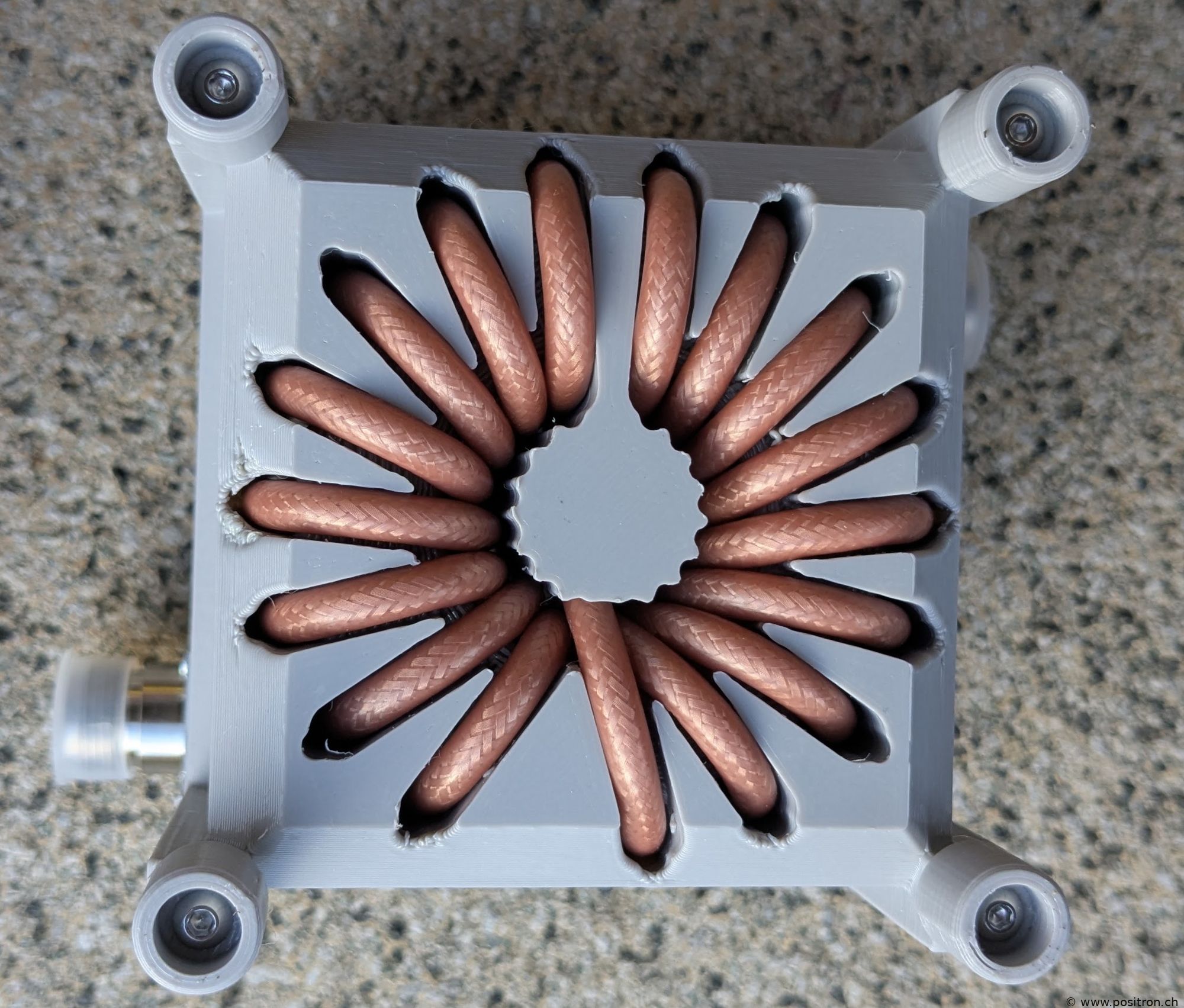
When the cable is simply wound onto the toroid and secured with cable ties, it touches the core and adjacent turns often contact each other. My idea: by defining the cable positions with a 3D-printed former, I can precisely control all spacings. The plastic in the gaps has a higher dielectric constant than air (PETG εr ≈ 2.5), but the spacing is well controlled. This also creates a defined gap between the cable and the toroid core.
| Suggestions by G3TXQ. Connecting all three combinations in series can be disadvantageous – suppressing unwanted resonances requires real resistive loss, not just reactance. However, since I need the wide frequency coverage, I accept a potentially less optimal suppression ratio. | 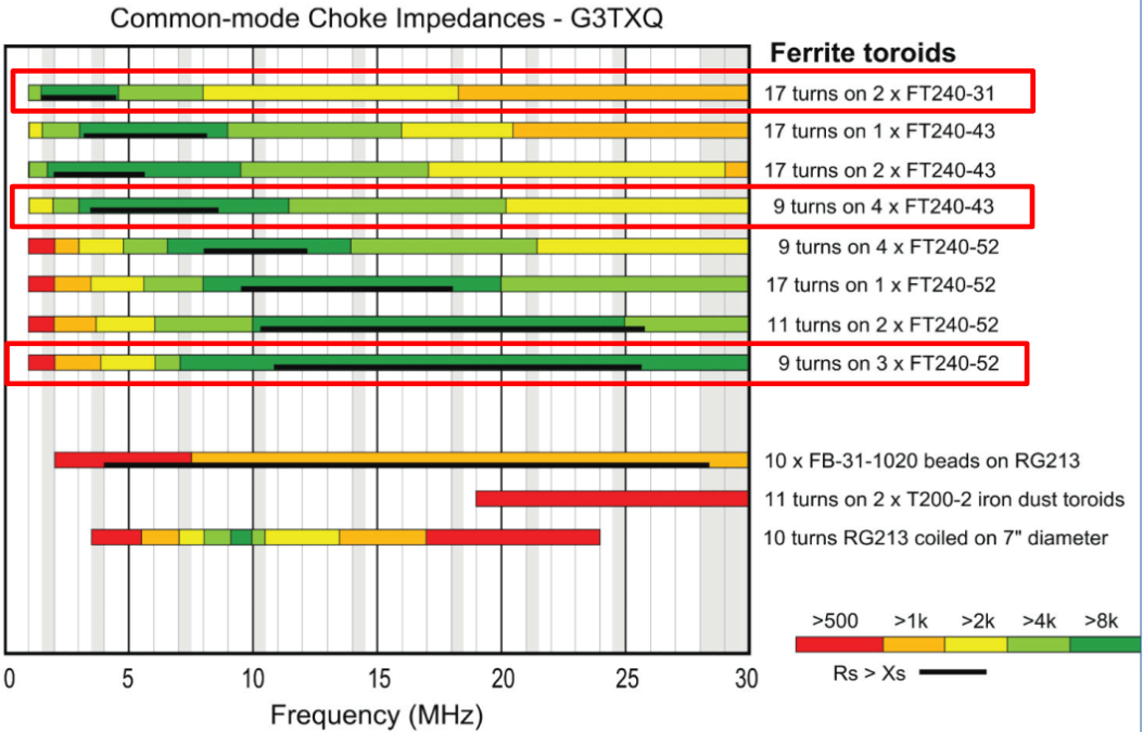 |
| 3D model. The toroids sit in a recessed pocket. Cable channels maintain spacing from the toroid core. The top section offers various options for mounting connectors. | 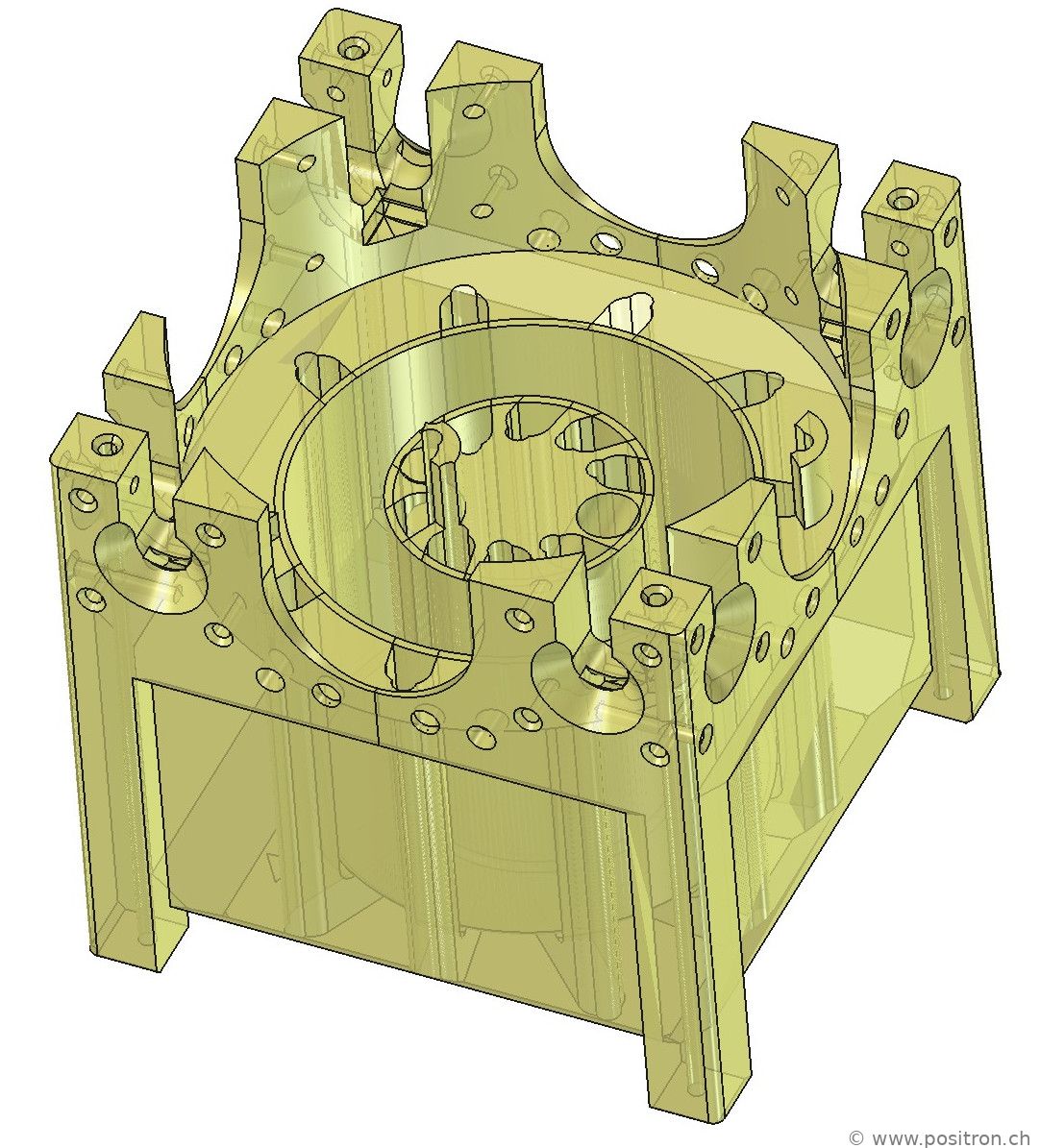 |
| With N-type connectors and a lid. Openings remain at the bottom and sides for ventilation. | 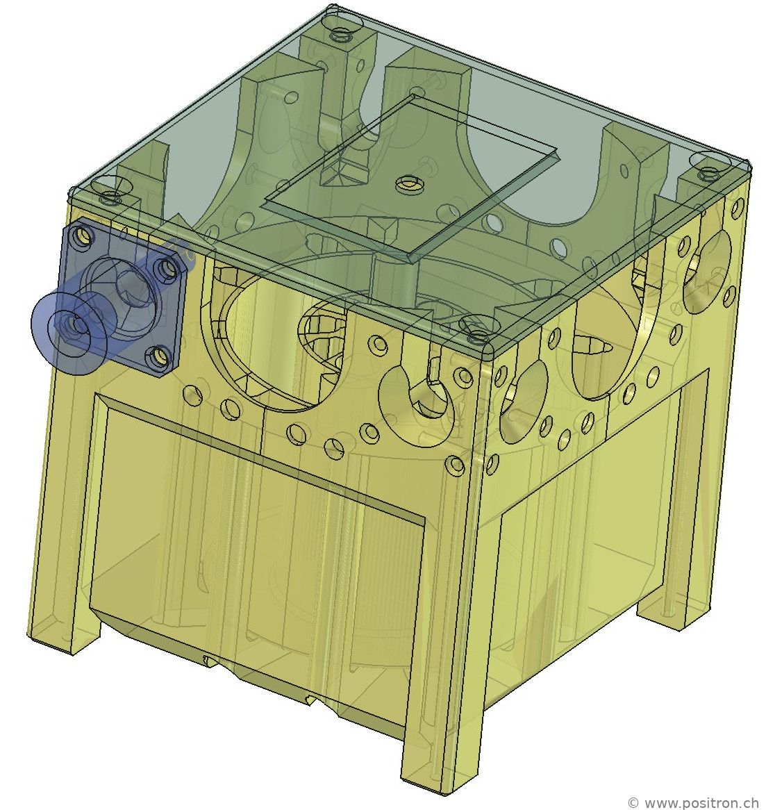 |
| View from below. Designing these channels was quite challenging. | 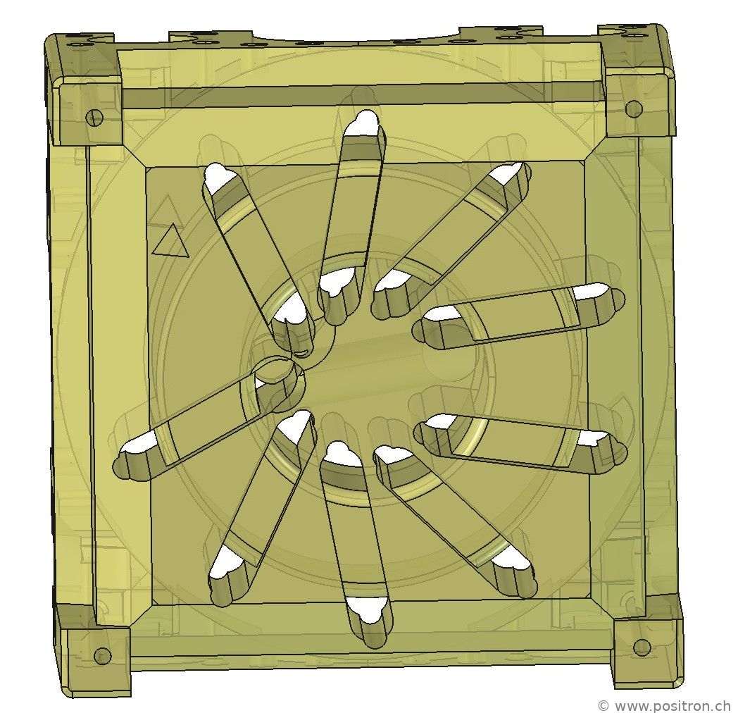 |
| Various toroids. | 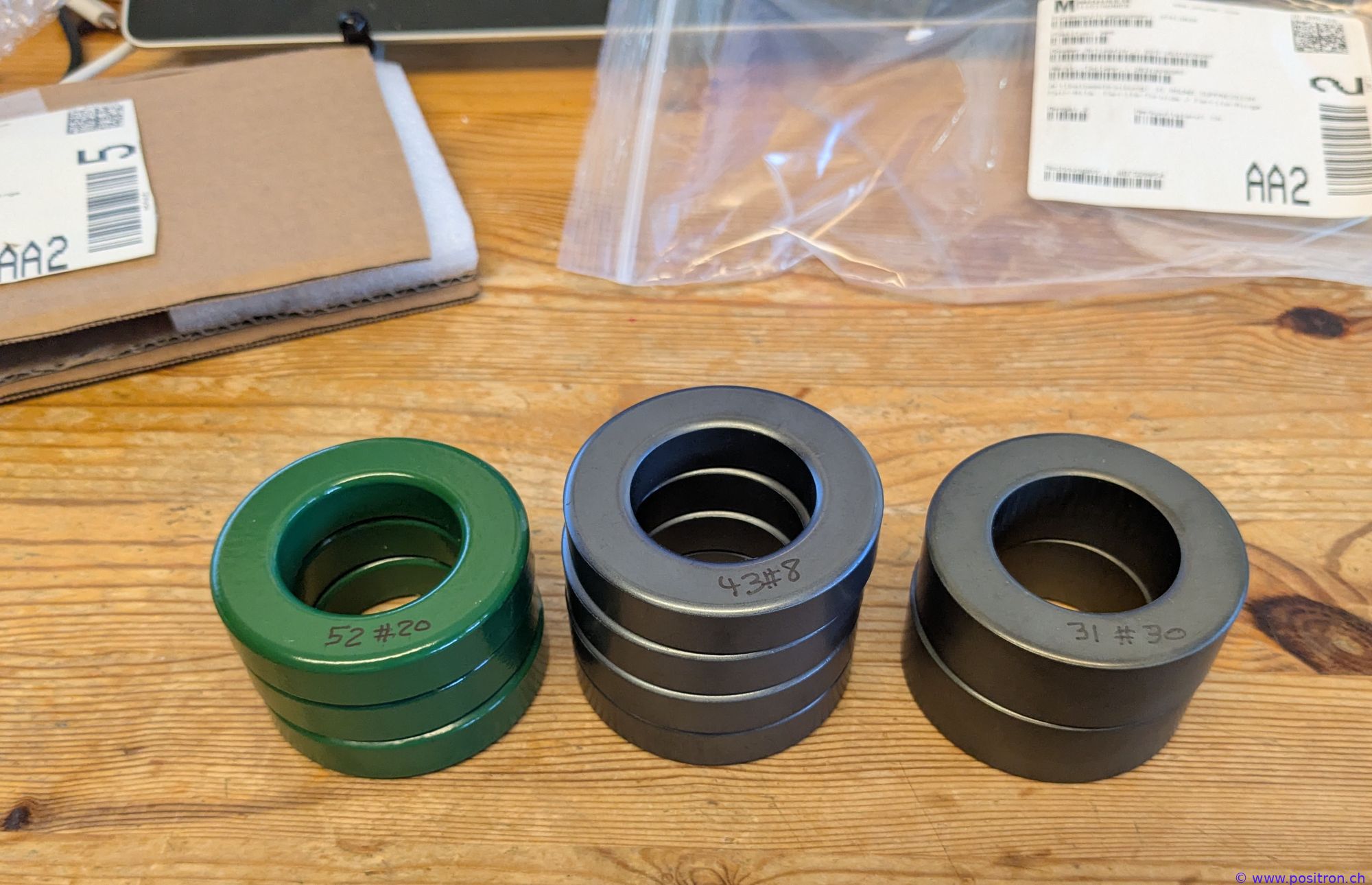 |
| 3D-printed part made from PETG. | 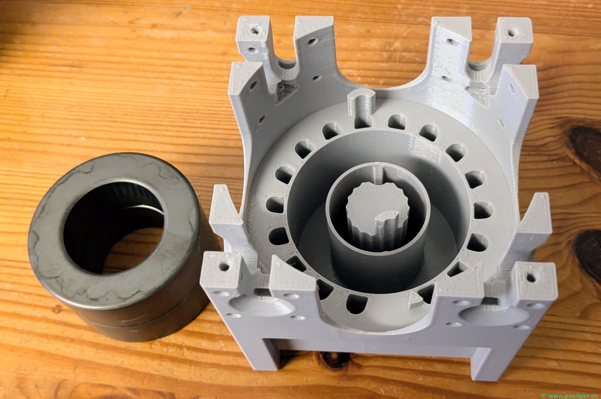 |
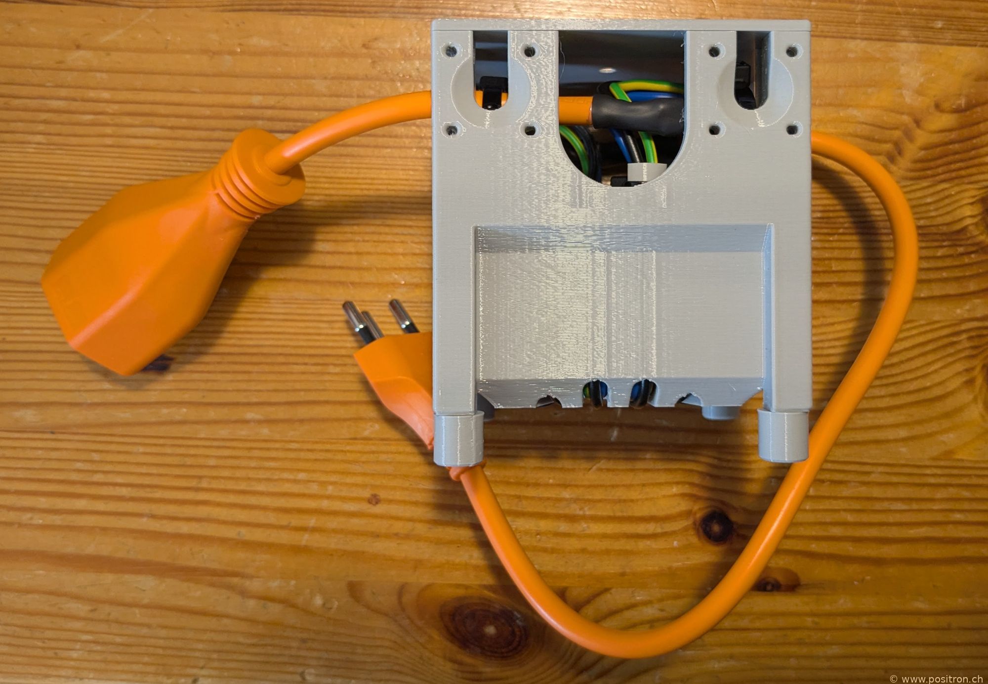
| A mains filter using 3 × 1.5 mm² installation wire. | 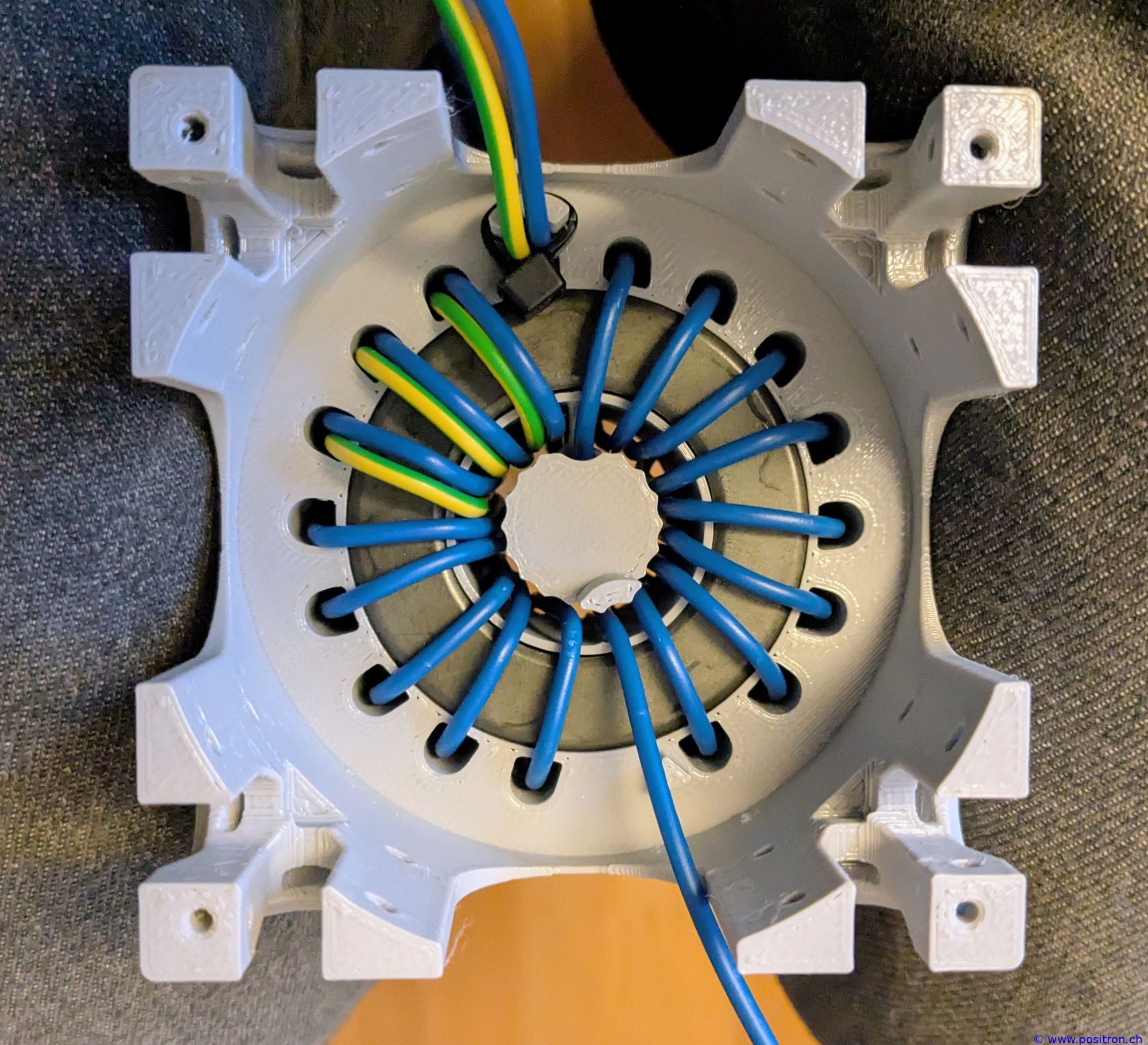 |
| Wires pulled through one at a time. Mains cable soldered on. | 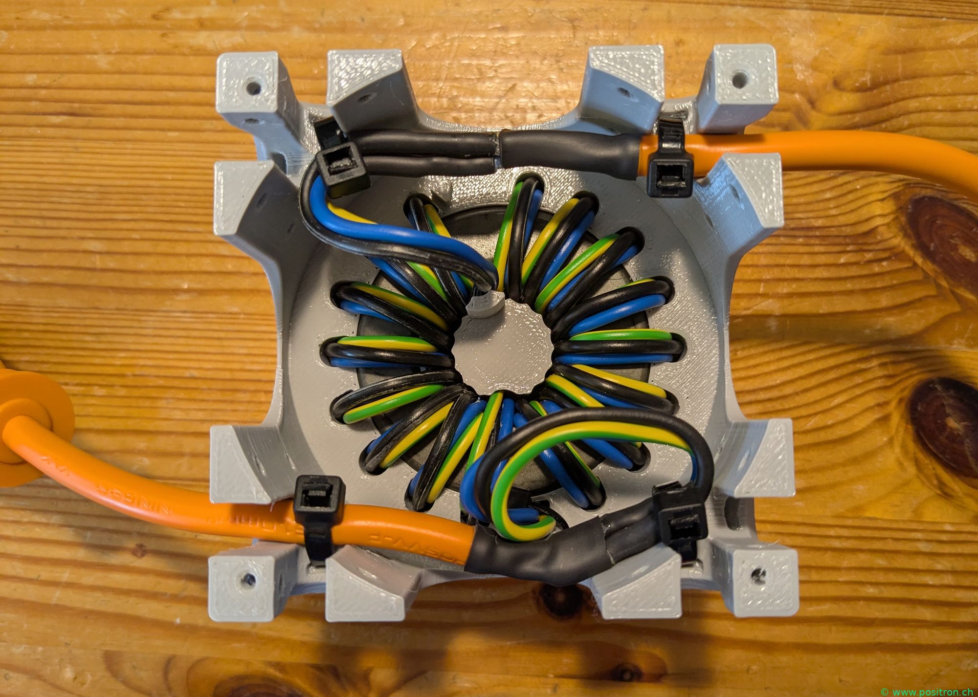 |
 |
|
| Combination of three choke filters. | 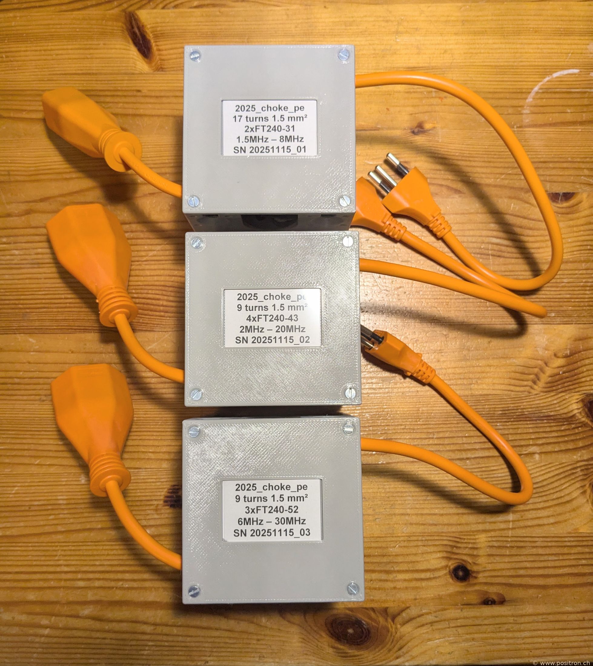 |
| A coaxial choke wound with RG-400. Important: do not use RG-400! Hyperflex 5 by Messi & Paoloni is far better suited. | 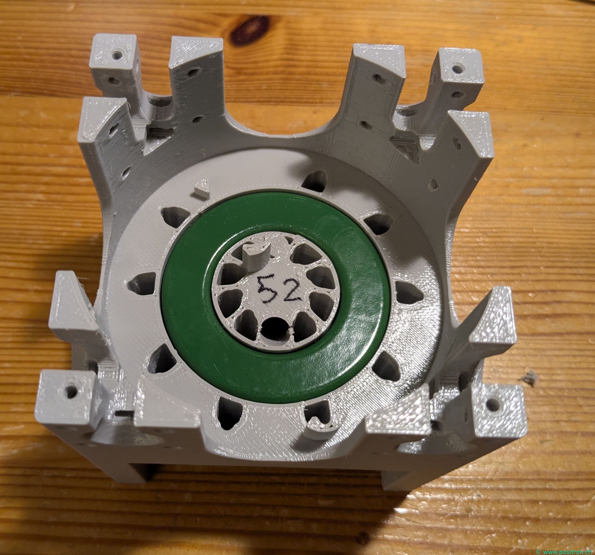 |
| View from below. | 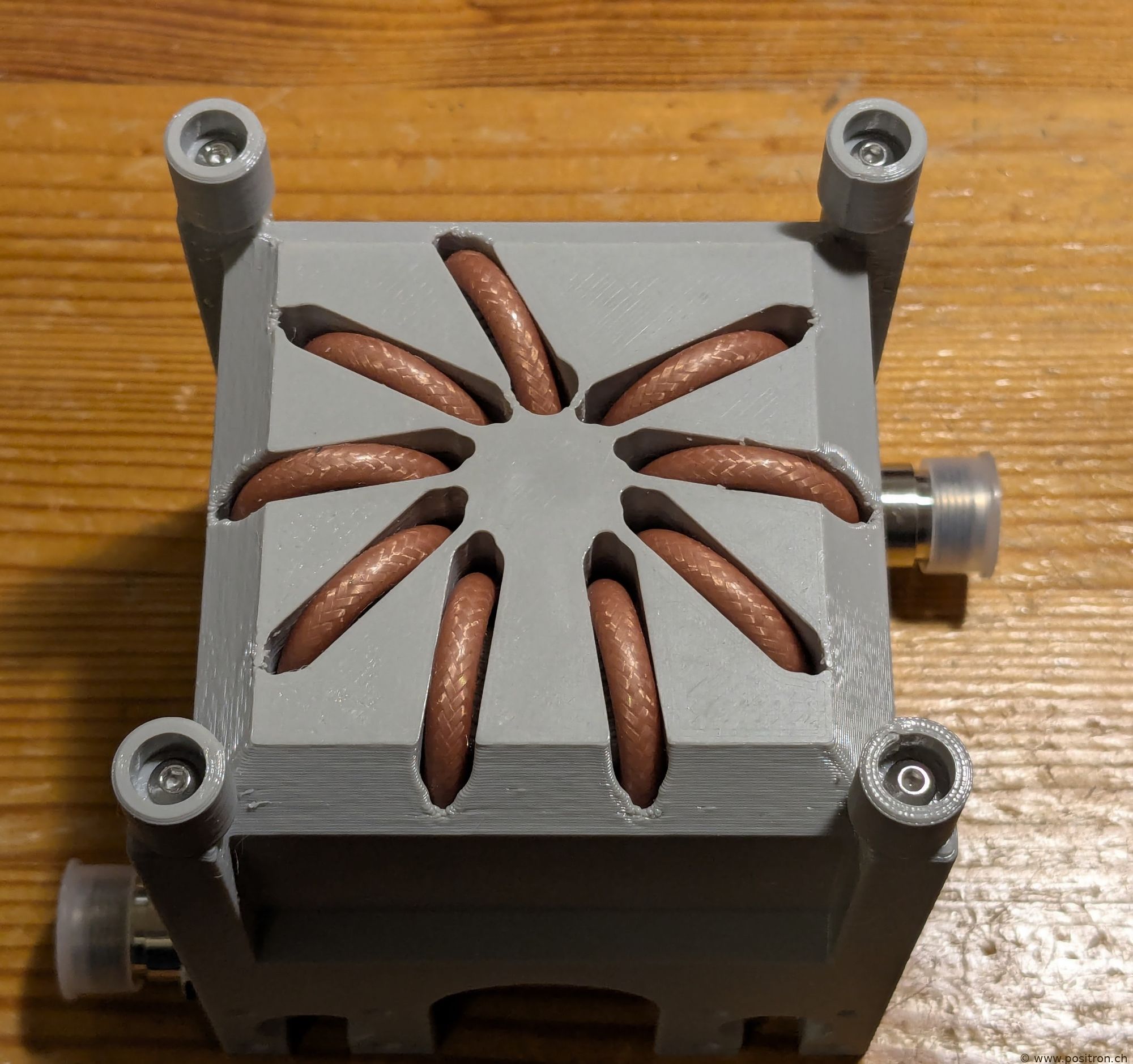 |
| With fully assembled connectors. | 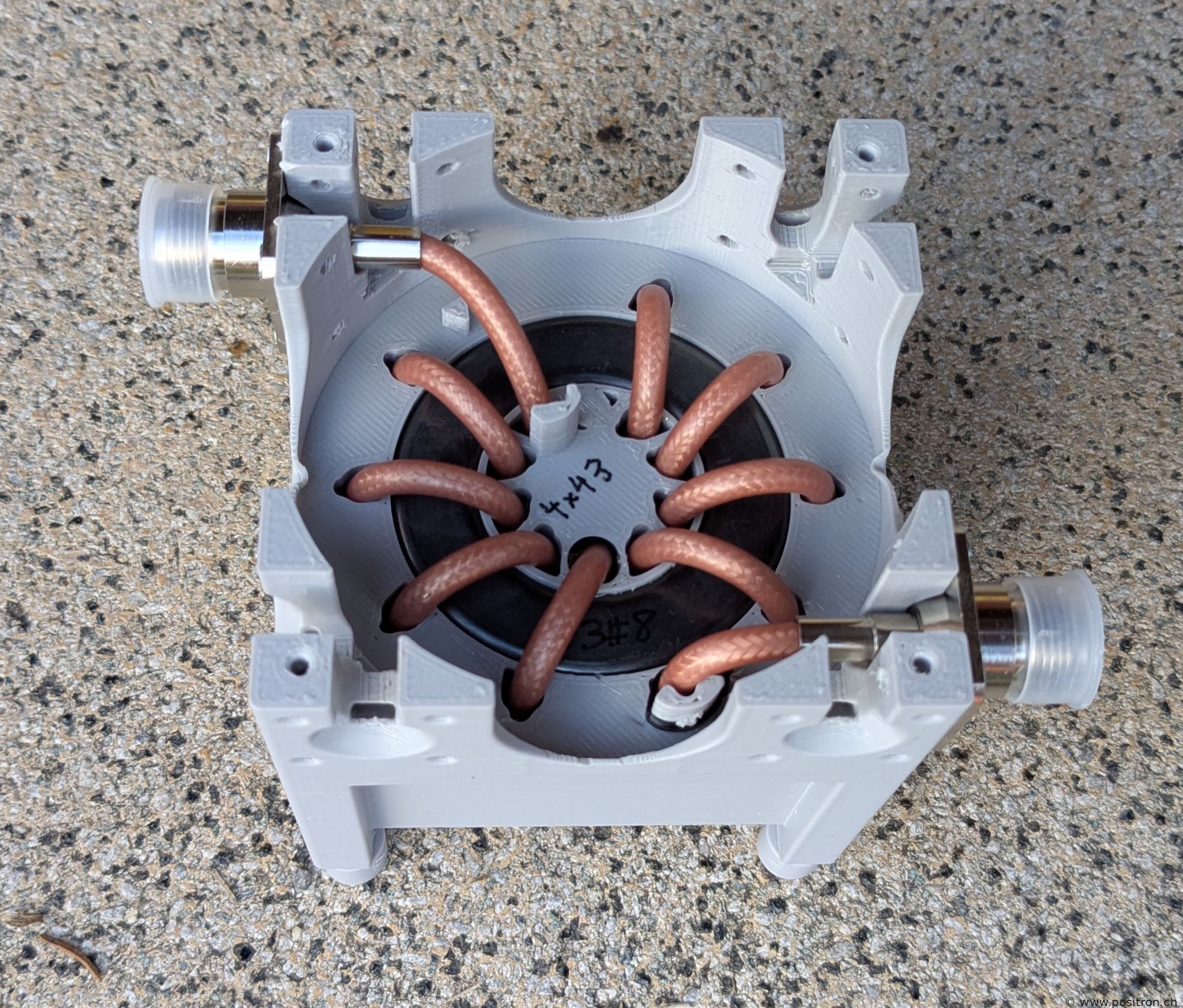 |
 |
|
| Completed individual filters. | 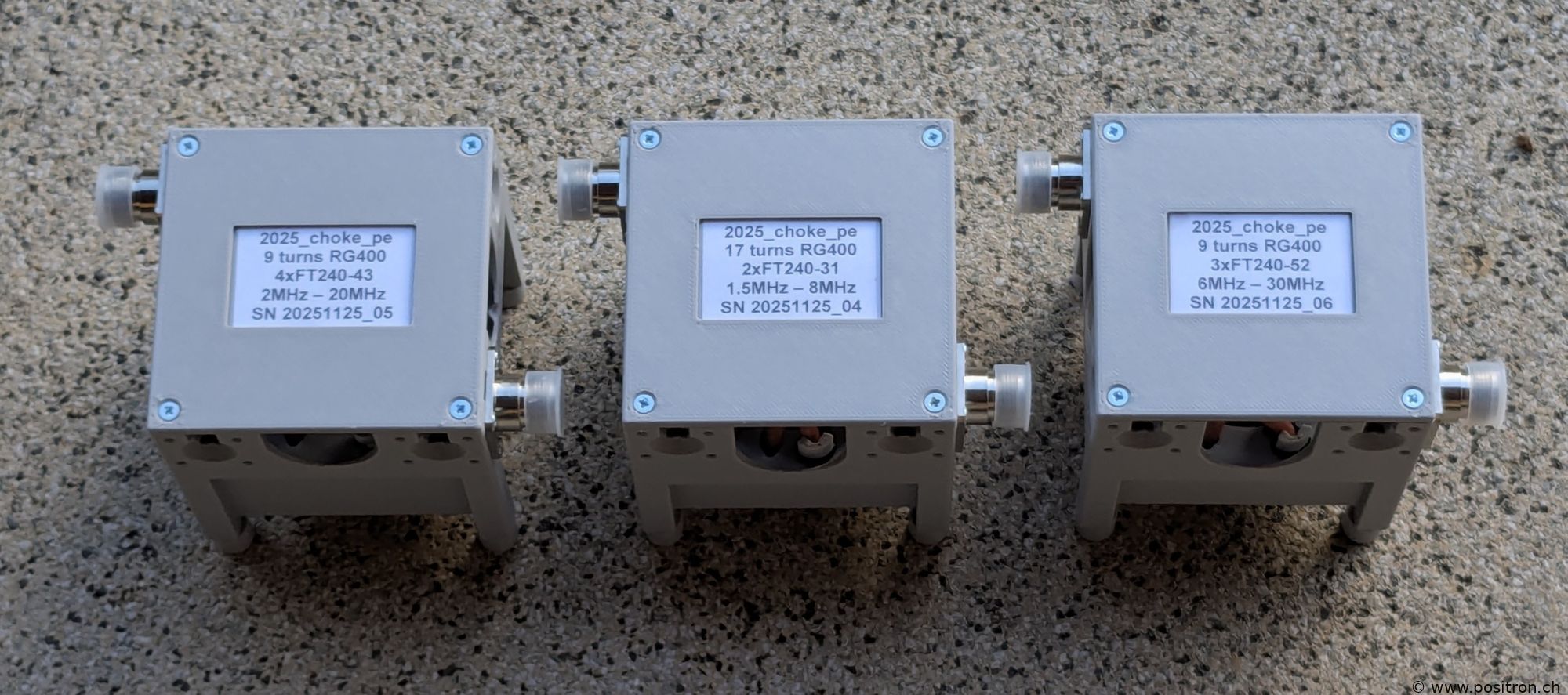 |
| Filter combination built with Hyperflex 5 by Messi & Paoloni. The cable is very easy to pull through thanks to its flexibility, and it has significantly lower losses. | 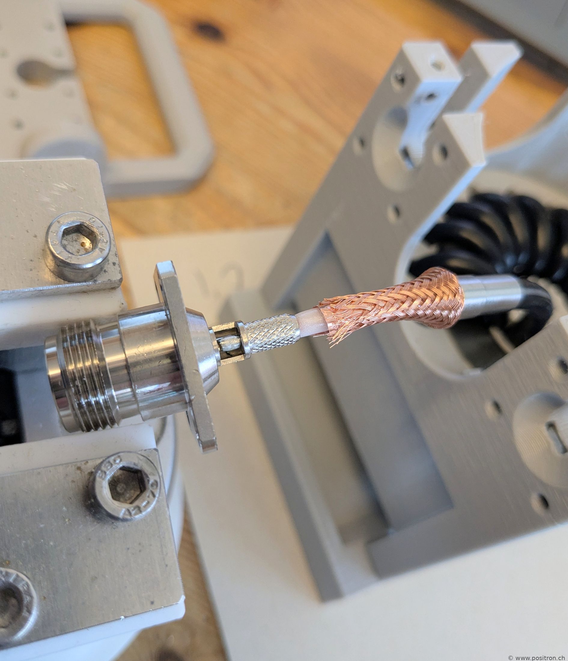 |
| Crimping the connectors. | 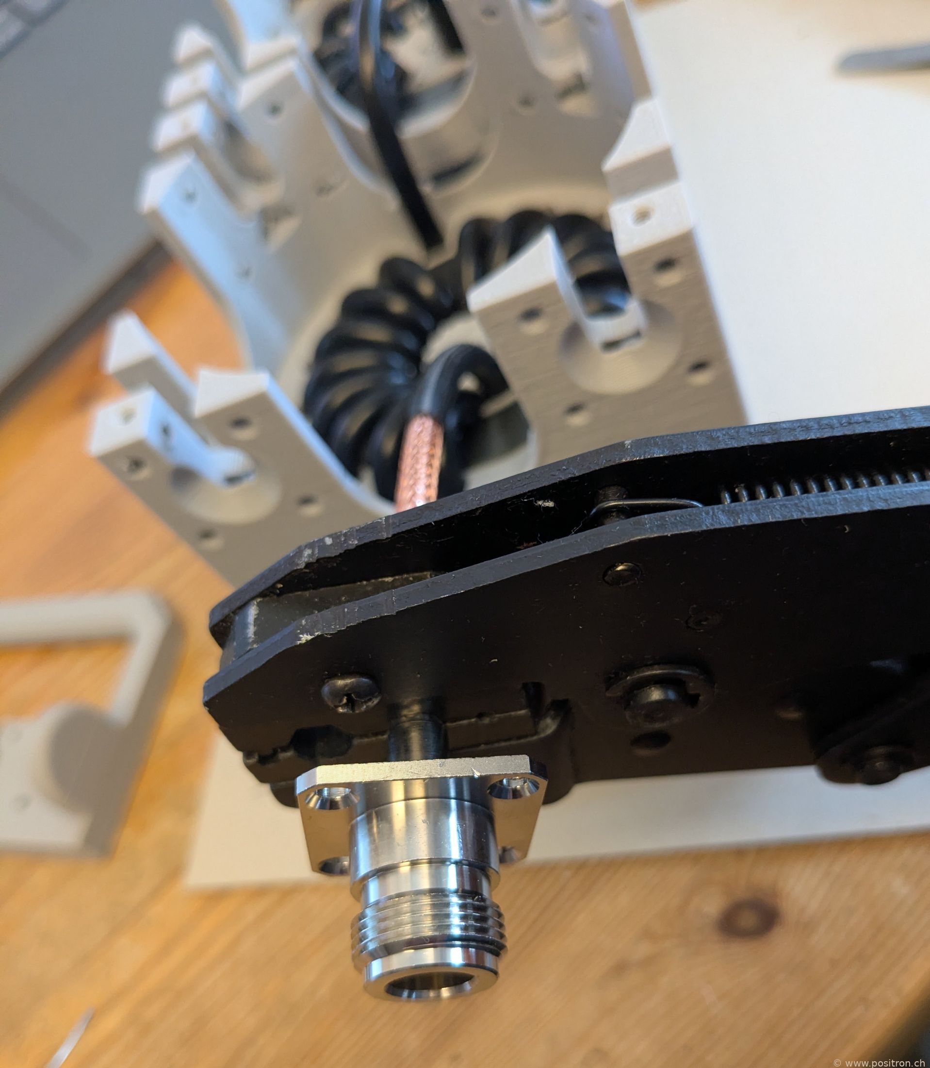 |
| All three filters bolted together. The cable runs straight through all three filters in one piece – fewer connector joints means lower losses. | 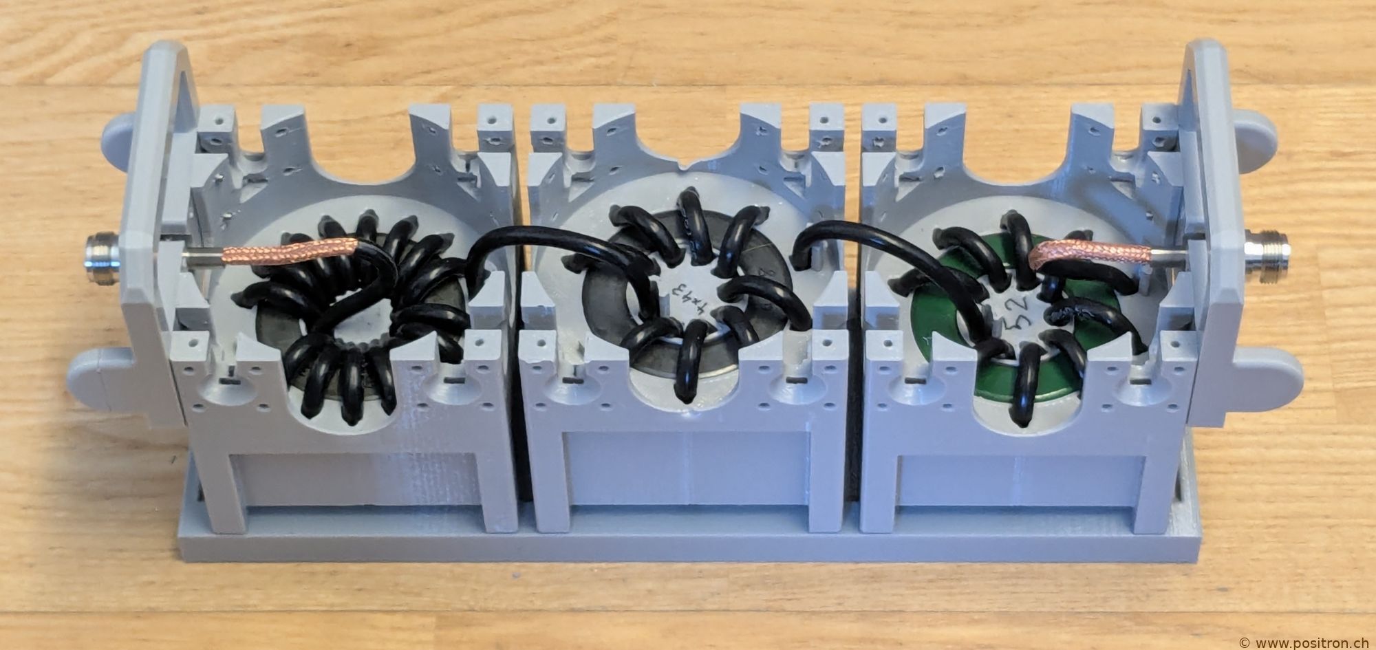 |
| Completed ferrite filter combination. | 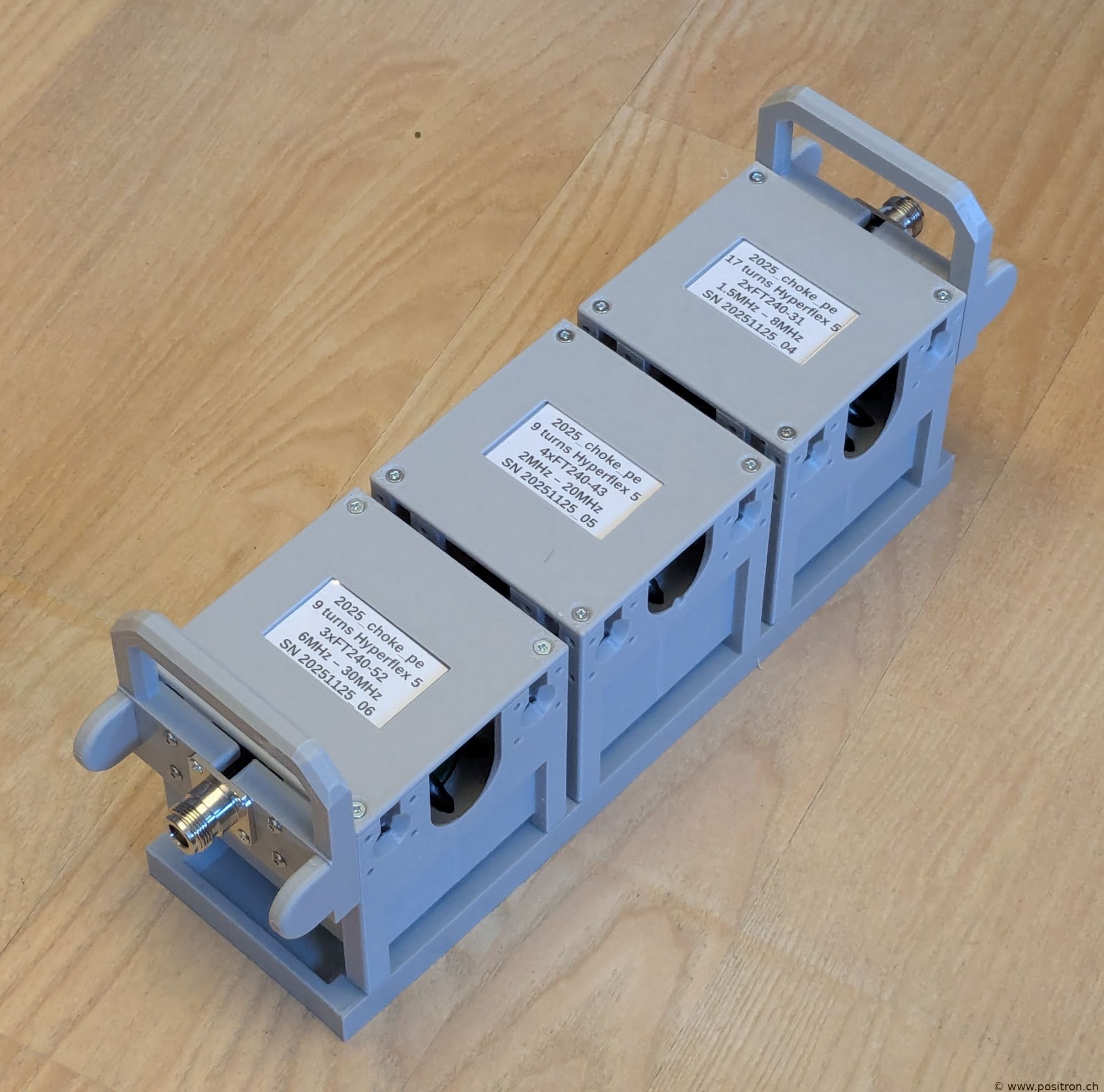 |
| Coaxial filter and control line filter side by side. | 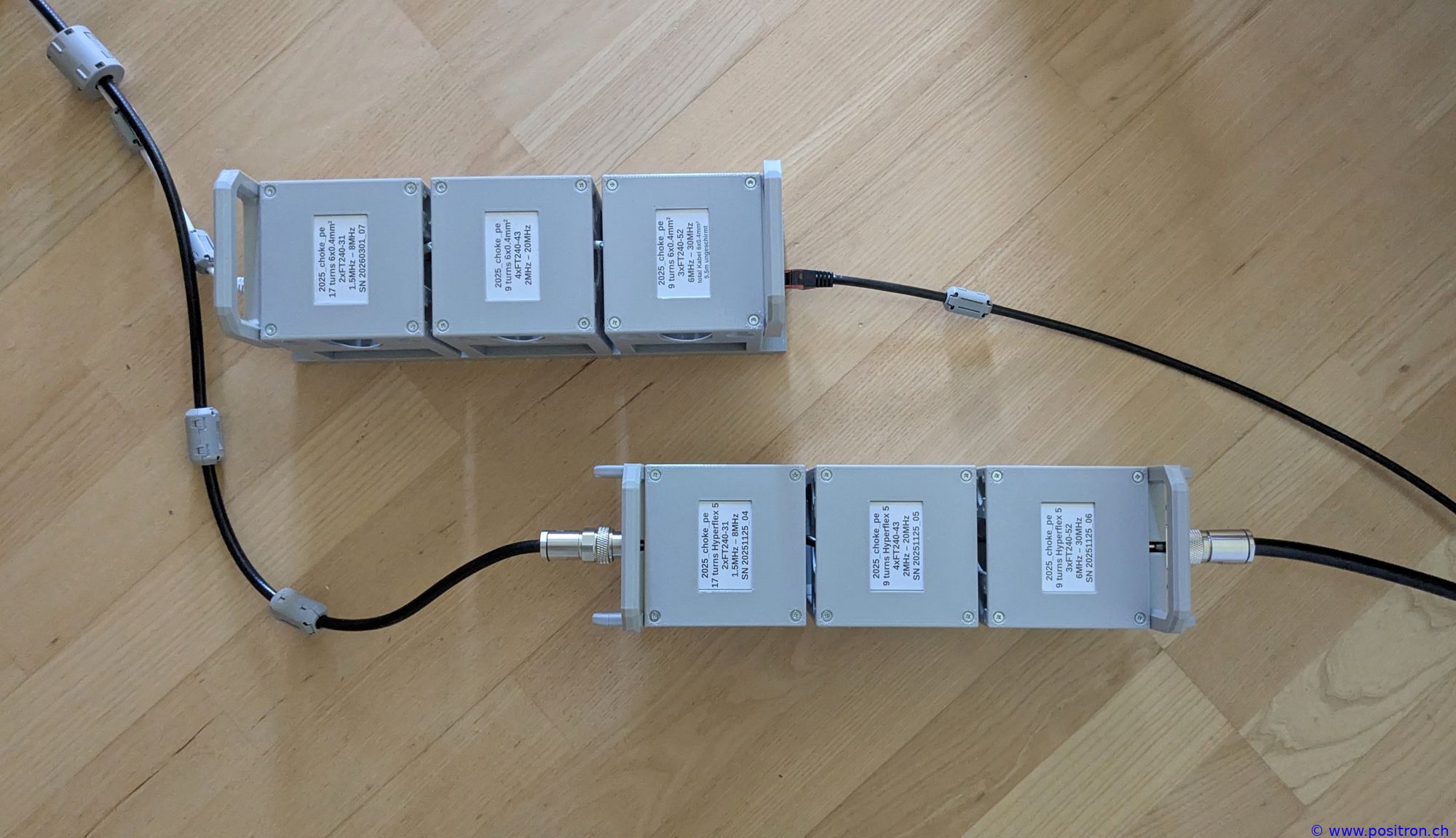 |
| Signal cable with 6 × 0.4 mm² conductors. |  |
| This cable is used as a control line for a magnetic loop antenna. To simplify winding, each conductor is wound individually and the wires are soldered together in between. Losses are negligible here. | 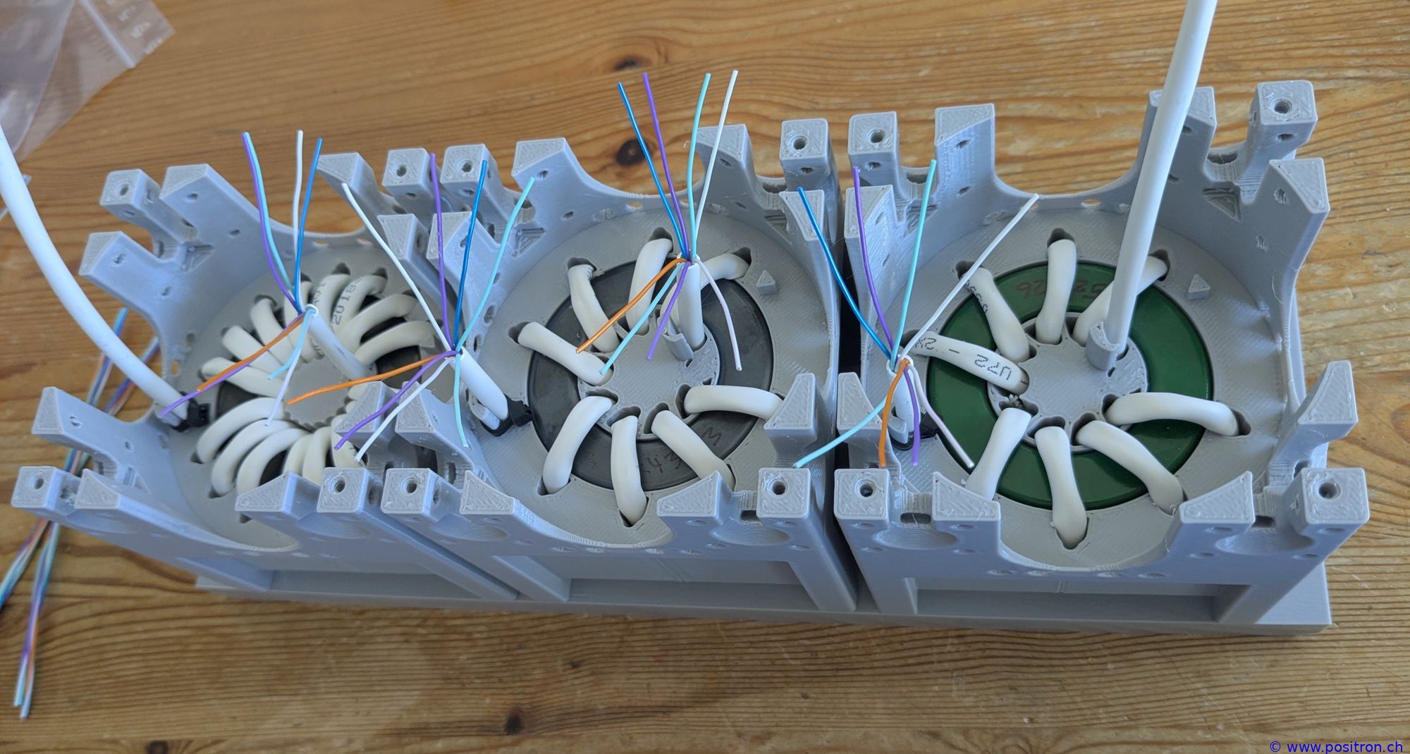 |
 |
|
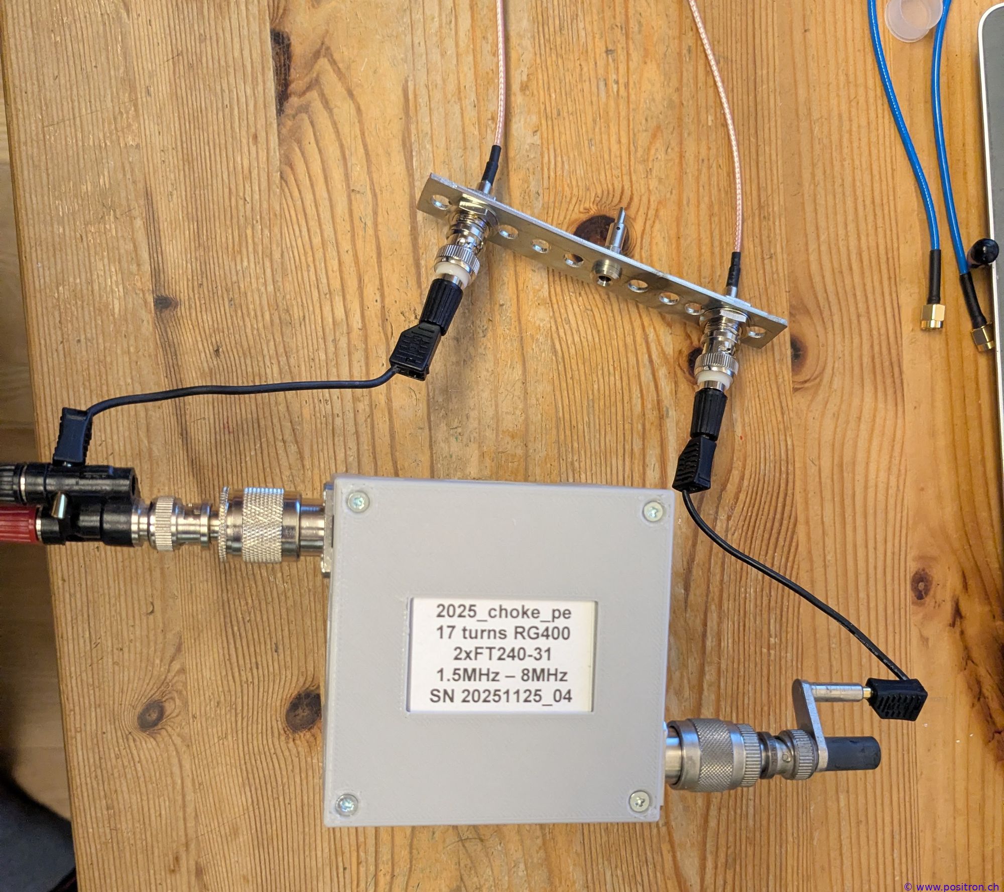
| Measuring several chokes. One method is to measure S21 from one end to the other. I built an adapter from a heavy copper busbar that connects and mechanically supports the two BNC ports. I calibrate the VNA and then measure the choke. | 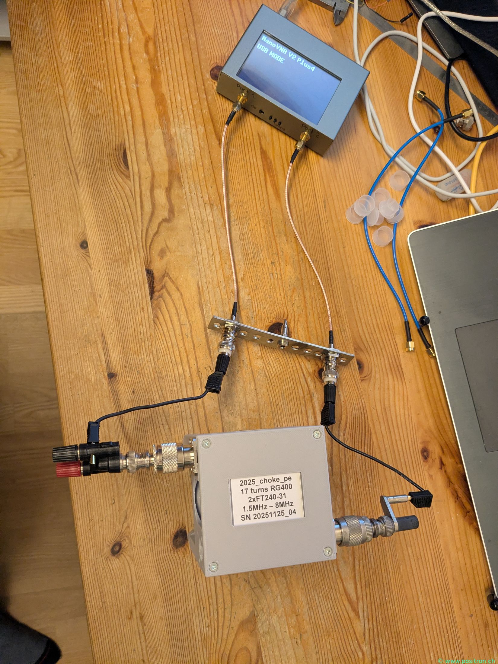 |
 |
|
|
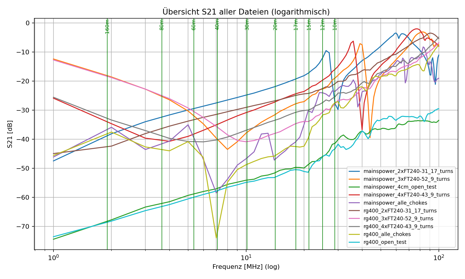
Measurements of the individual toroids and of the full combination “...all_chokes”.
In the “...open_test” measurements, only the black banana cables are connected in approximately the same position as during choke measurements – this captures their residual capacitance. The individual mains cable filters show noticeable peaks around 28 MHz, where the connecting cables are longer. These are most likely resonances of the connecting cables and have little to do with the actual choke. The measured combination no longer shows these peaks. At the final installation site, the chokes are spaced apart in a daisy chain, which should improve matters further. |
 |
|
The combined filter achieves an S21 of lower than −20 dB across 1 MHz to 30 MHz. In the final installation, where the leads are not routed together back to the VNA, performance should be even better, especially at the higher frequencies. I consider this a good result. |
|