Home
Antennas
Various
> Attenuators
Broadband chokes
CW straight key selfmade
CW trainer
FT-991A output power
FT-991A cw envelope
Meter Nissei DG-503
Resistive Bridge
Insulation Tester 6688B
Linear Supply PT110A
Impressum
Sitemap
Printable version
Measurement of two attenuators
I purchased a used attenuator. Model JFW 50FA0-030-100
Presumably it has the following specifications:
| Connectors | Type N | |
| Attenuation | 30 | dB |
| Impedance | 50 | Ohm |
| Continuous power | 100 | W |
| Frequency range | 0 to 3 | GHz |
| The attenuator could for example be implemented as a pi network. Looking into the input, you see 50 ohm impedance from both the left and the right side. |  |
| The attenuator is heavy and round, impractical because it rolls off the table. I therefore screwed feet onto both sides. These also protect the connectors. |  |
 |
|
| Type N connector, female side. |  |
| Type N connector, male side. | 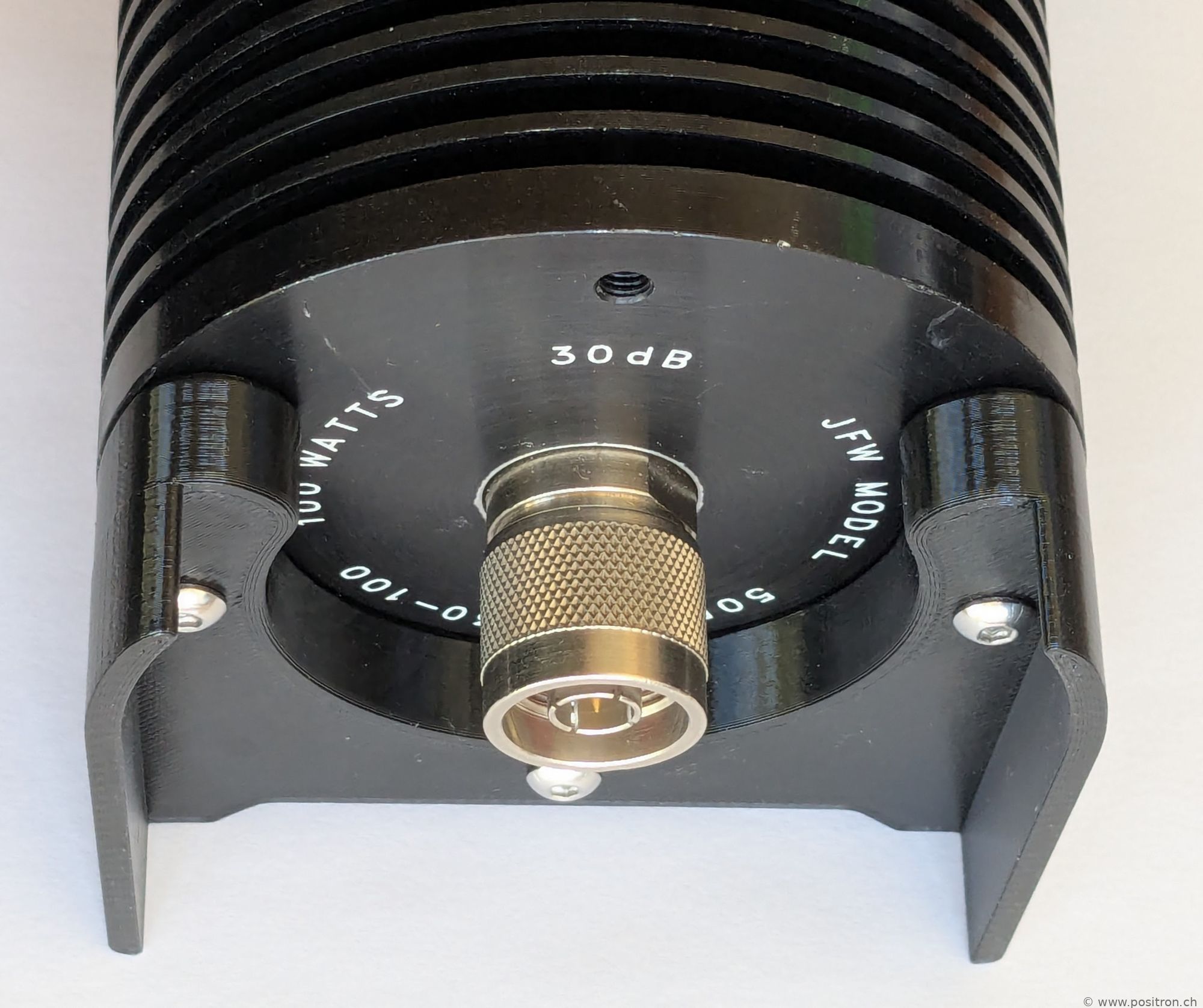 |
|
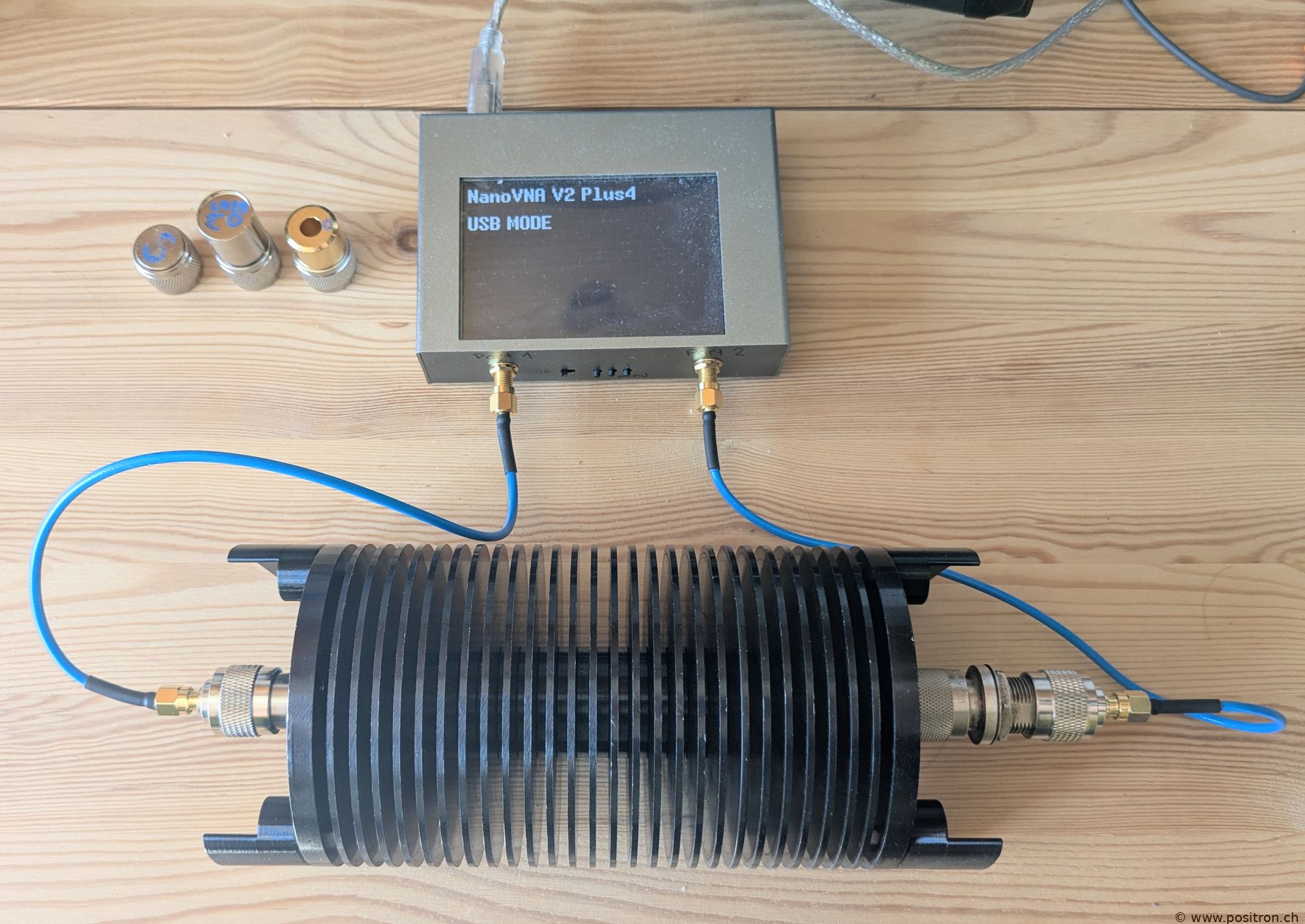
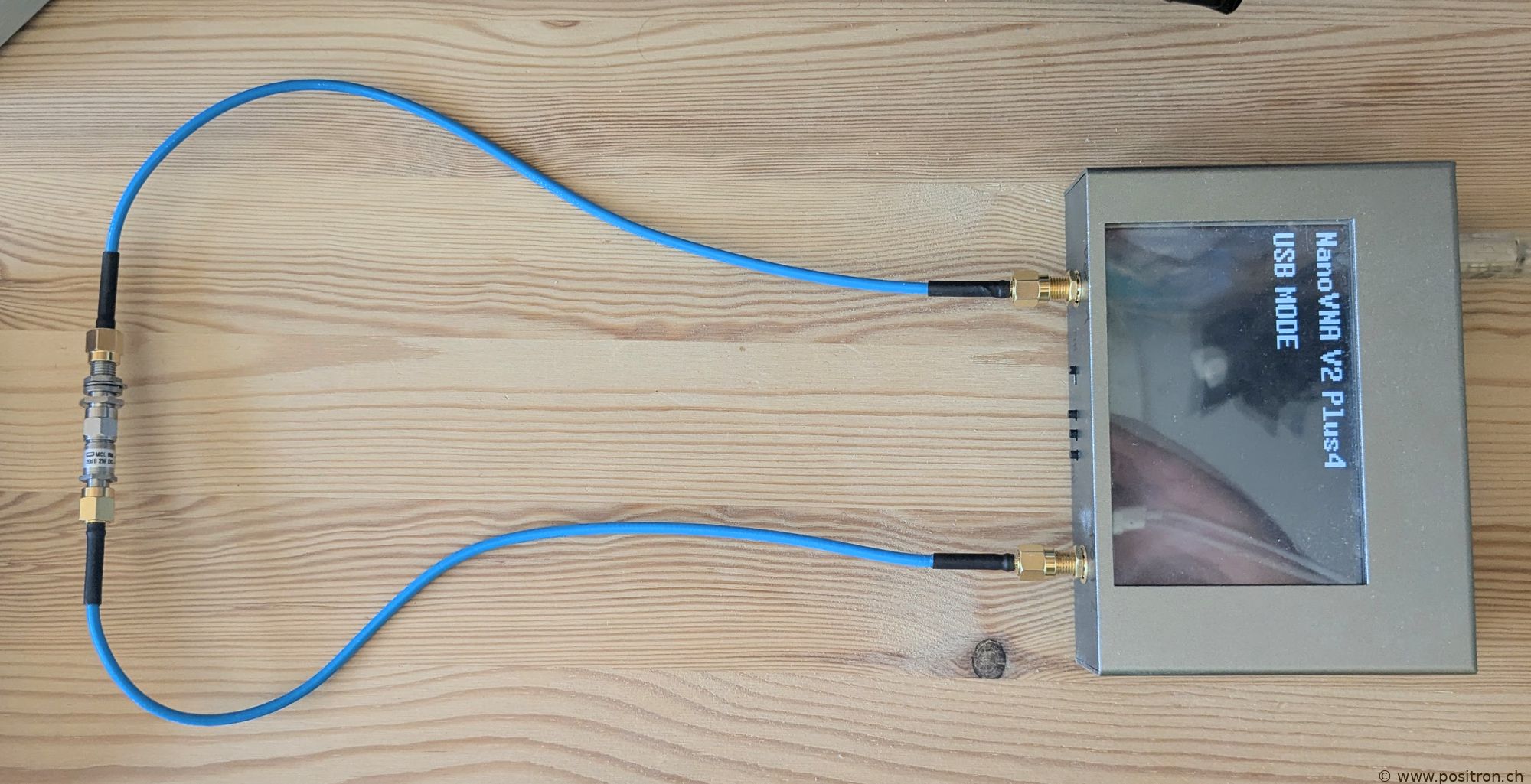
I measure the attenuation using an affordable NanoVNA V2 Plus4.
Before the measurement, the VNA is of course calibrated. |
 |
| Attenuation from male side to female side. 100 kHz to 300 MHz. The attenuation is very accurate. The datasheet specifies +-0.5 dB DC to 3 GHz. | 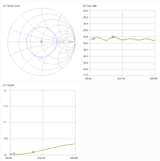
|
| Attenuation from female side to male side. 100 kHz to 300 MHz. The attenuation is very accurate. The datasheet specifies +-0.5 dB DC to 3 GHz. | 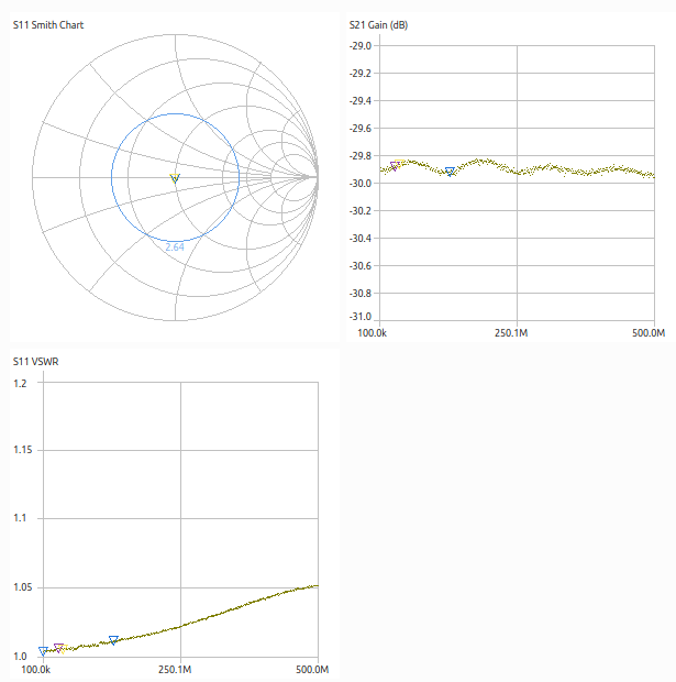
|
|
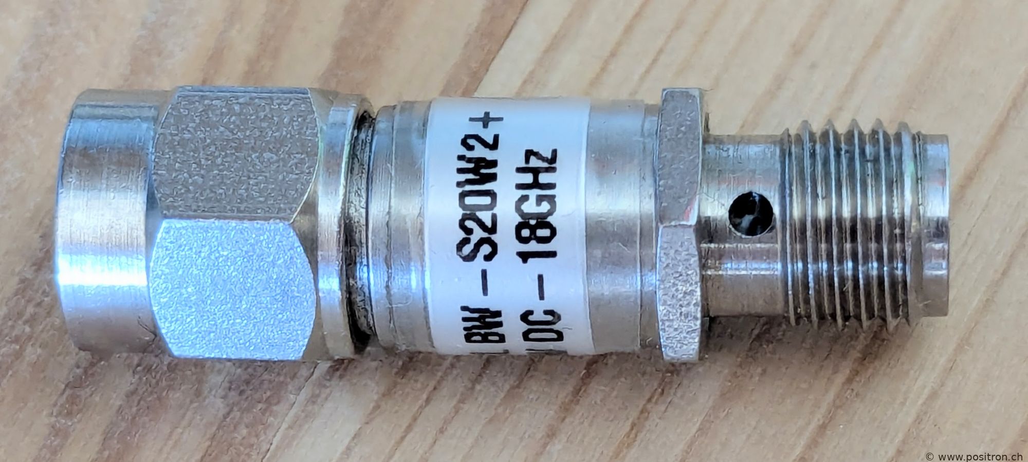
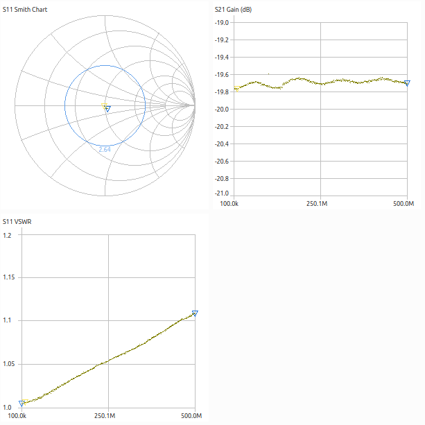
Additionally, I measure a very small attenuator. Mini Circuits, MCL-BW S20W2+ 20dB 2W DC-18GHz 0843. The datasheet specifies -0.5 dB to +0.8 dB from DC to 18 GHz. The measured deviation is smaller. |
 |
 |
|
|