Home
Antennas
Various
Attenuators
Broadband chokes
CW straight key selfmade
CW trainer
FT-991A output power
> FT-991A cw envelope
Meter Nissei DG-503
Resistive Bridge
Insulation Tester 6688B
Linear Supply PT110A
Impressum
Sitemap
Printable version
|
In CW mode, the RF transmit power is switched on and off in time with the Morse code characters. If the switching is not abrupt but gradual, adjacent frequencies are less disturbed. On my FT-991A I can configure the rise and fall times of CW keying. I did this and measured what the transmitter actually does. |
|
|
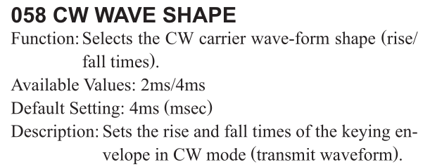
Excerpt from the FT-991A manual A time of 4 ms or 2 ms can be selected. |
 |
|
Ideally, the turn-on and turn-off are shaped with a raised cosine or even softer curves. Image right: raised cosine example, excerpt from a paper by Richard Harris G3OTK. Richard Harris G3OTK, Keyclicks Version 1 |
 |
|
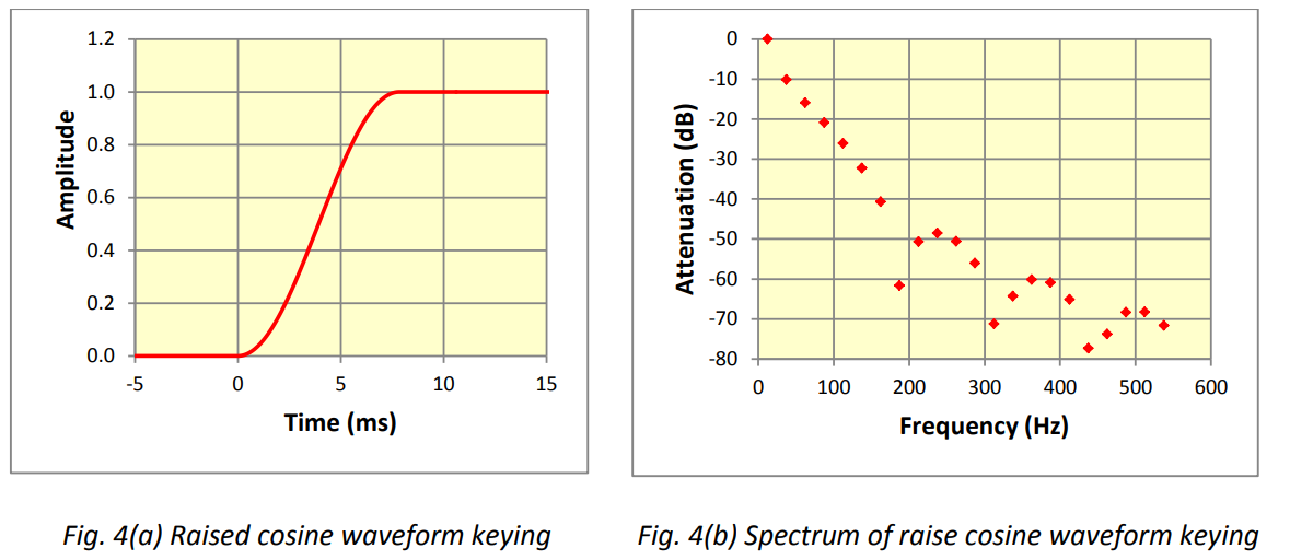
Setting option of my FT-991A. In the image, parameter 058 is set to 2 ms. I perform these tests on the 30 m band. |
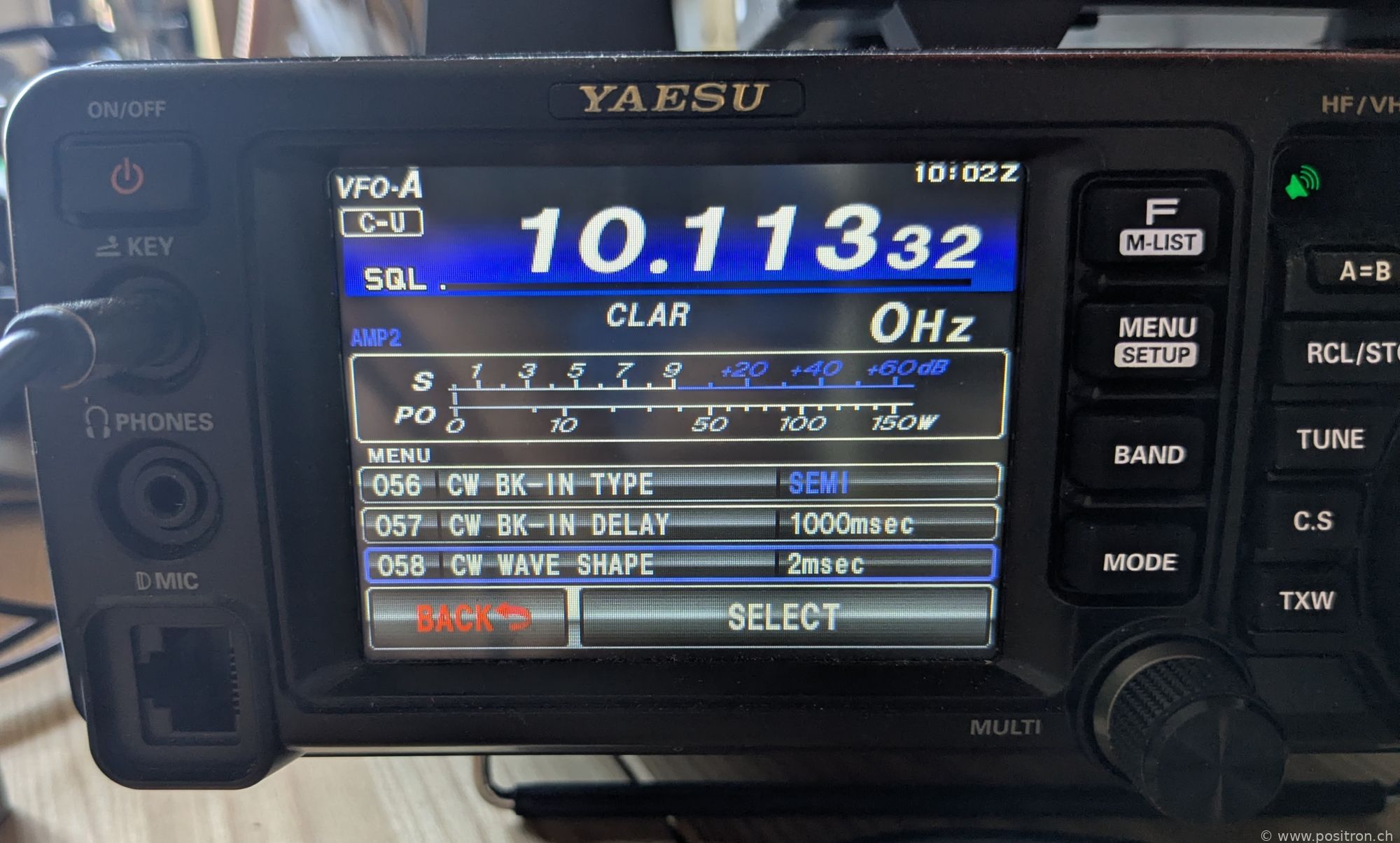 |
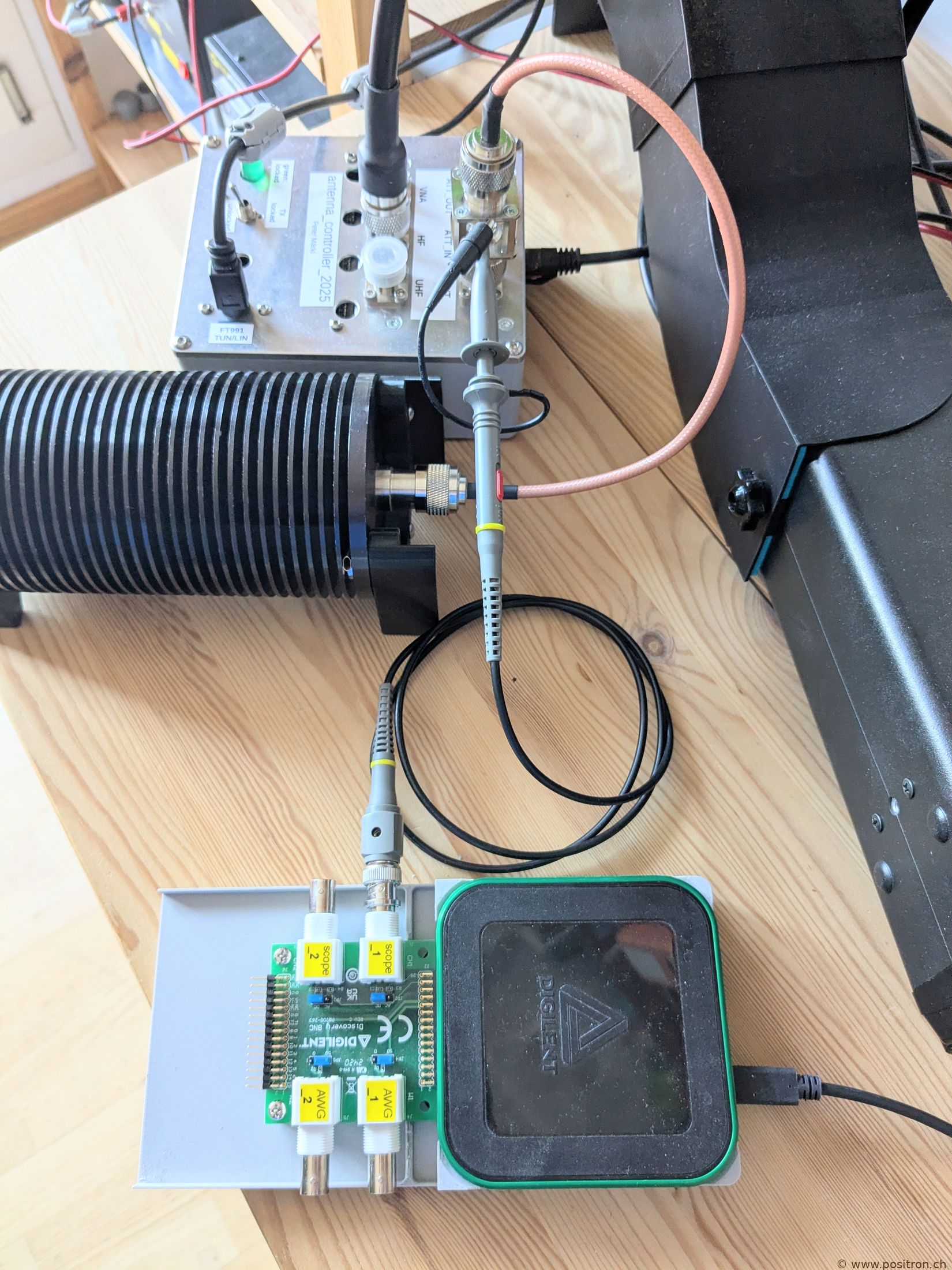
| Using an adapter made from two N-type connectors with a standoff bolt, I can tap the sense signal. |  |
|
I use an inexpensive P6100 probe, properly compensated. The load is a 100 W attenuator. I measure the signal with a Digilent AD3 oscilloscope. Sample Mode: Min/Max (for the envelope). I key manually with a straight key, so the pulses are not always exactly the same length. |
 |
|
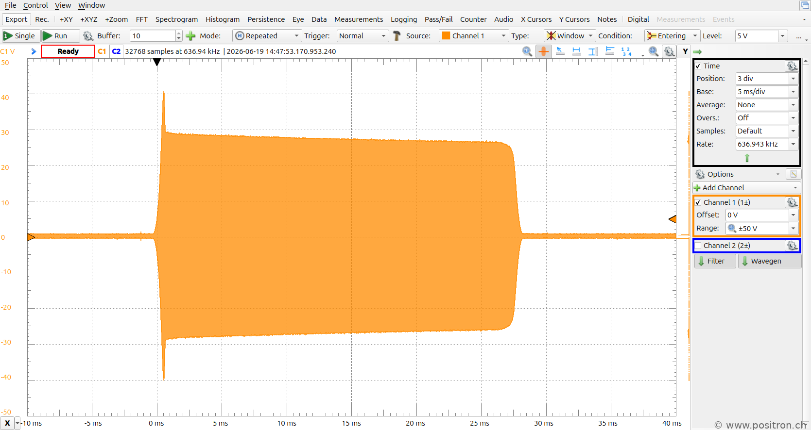
Setting: 2 ms and 5 W. The turn-on was not what I expected — a massive overshoot. That is unpleasant. The amplitude then slowly decreases. The turn-off looks quite nicely shaped by eye. I think something went seriously wrong during development. |
 |
| Setting: 4 ms and 5 W. I see a slightly slower transition. | 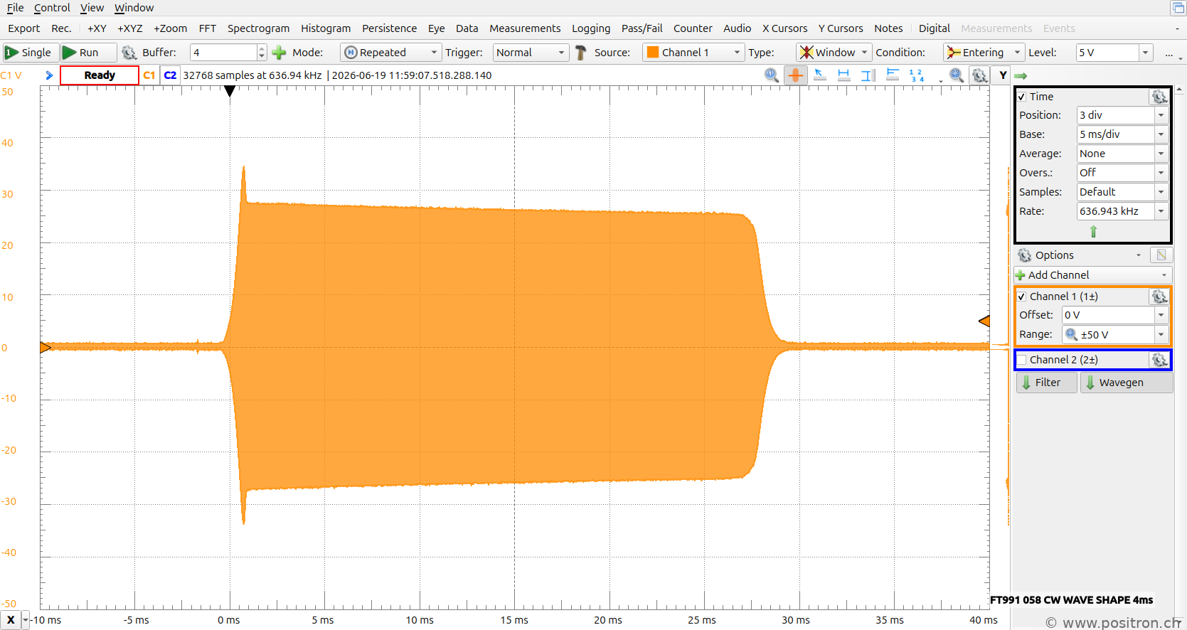 |
| Setting: 2 ms and 50 W. | 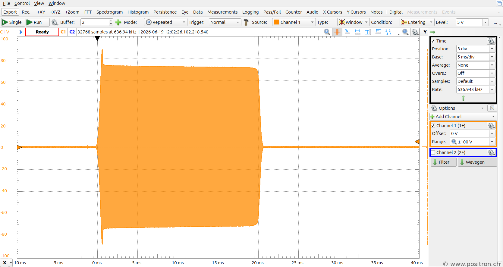 |
| Setting: 4 ms and 50 W. | 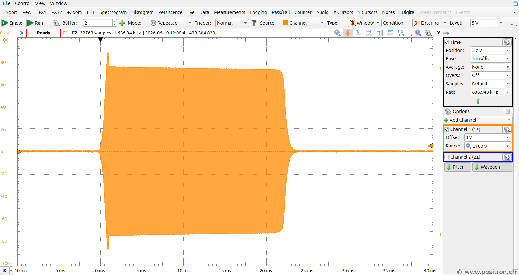 |
| Setting: 2 ms and 100 W. | 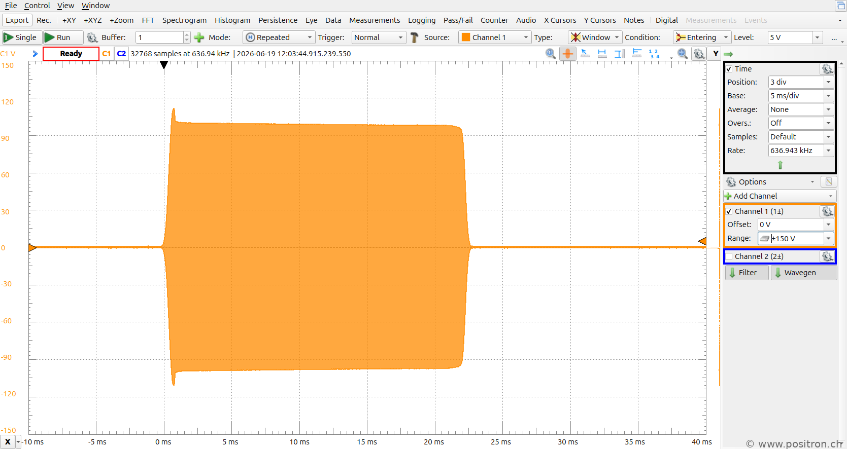 |
| Setting: 4 ms and 100 W. | 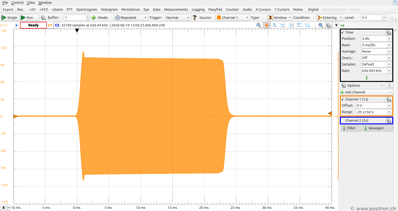 |
|
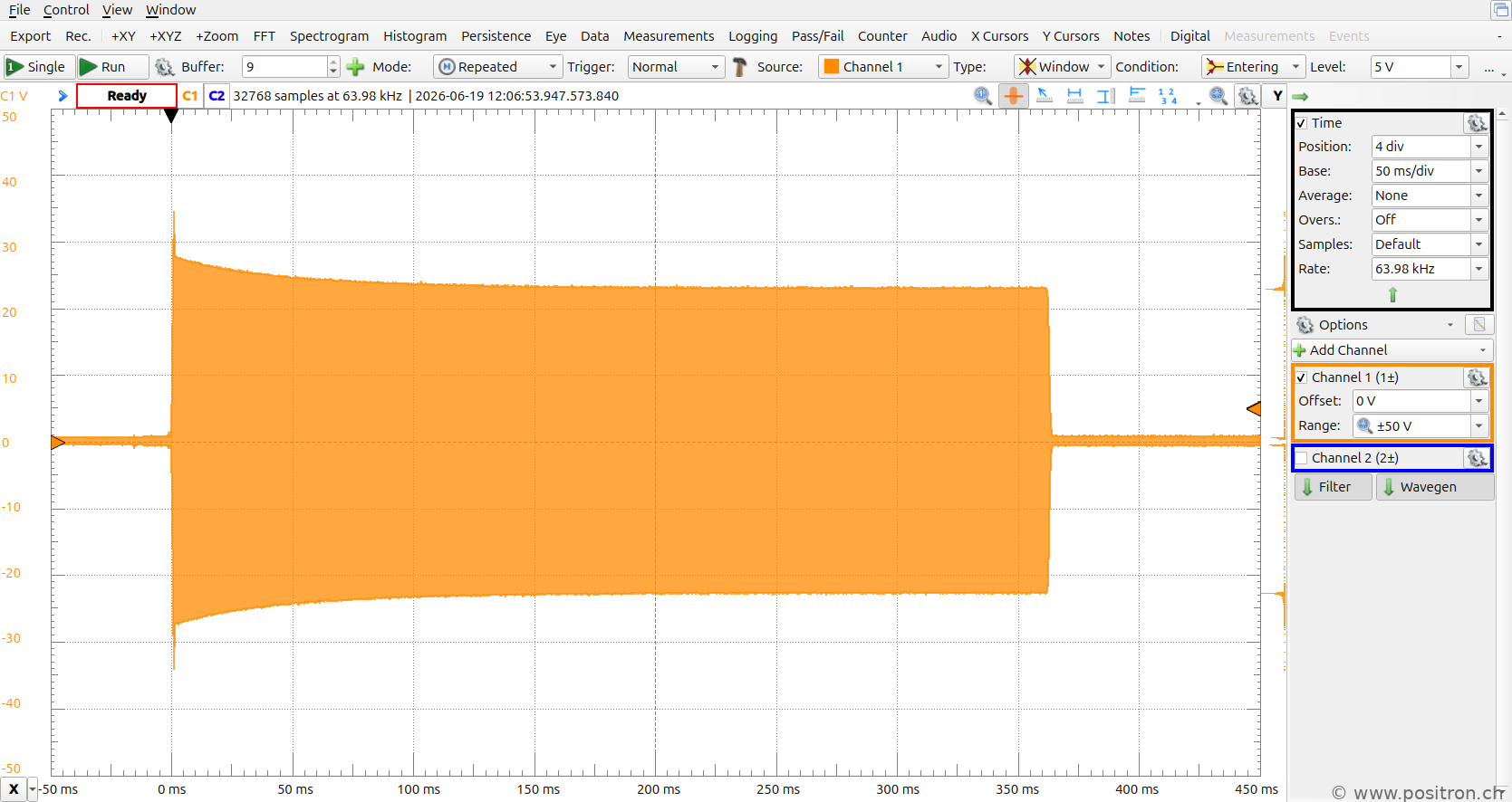
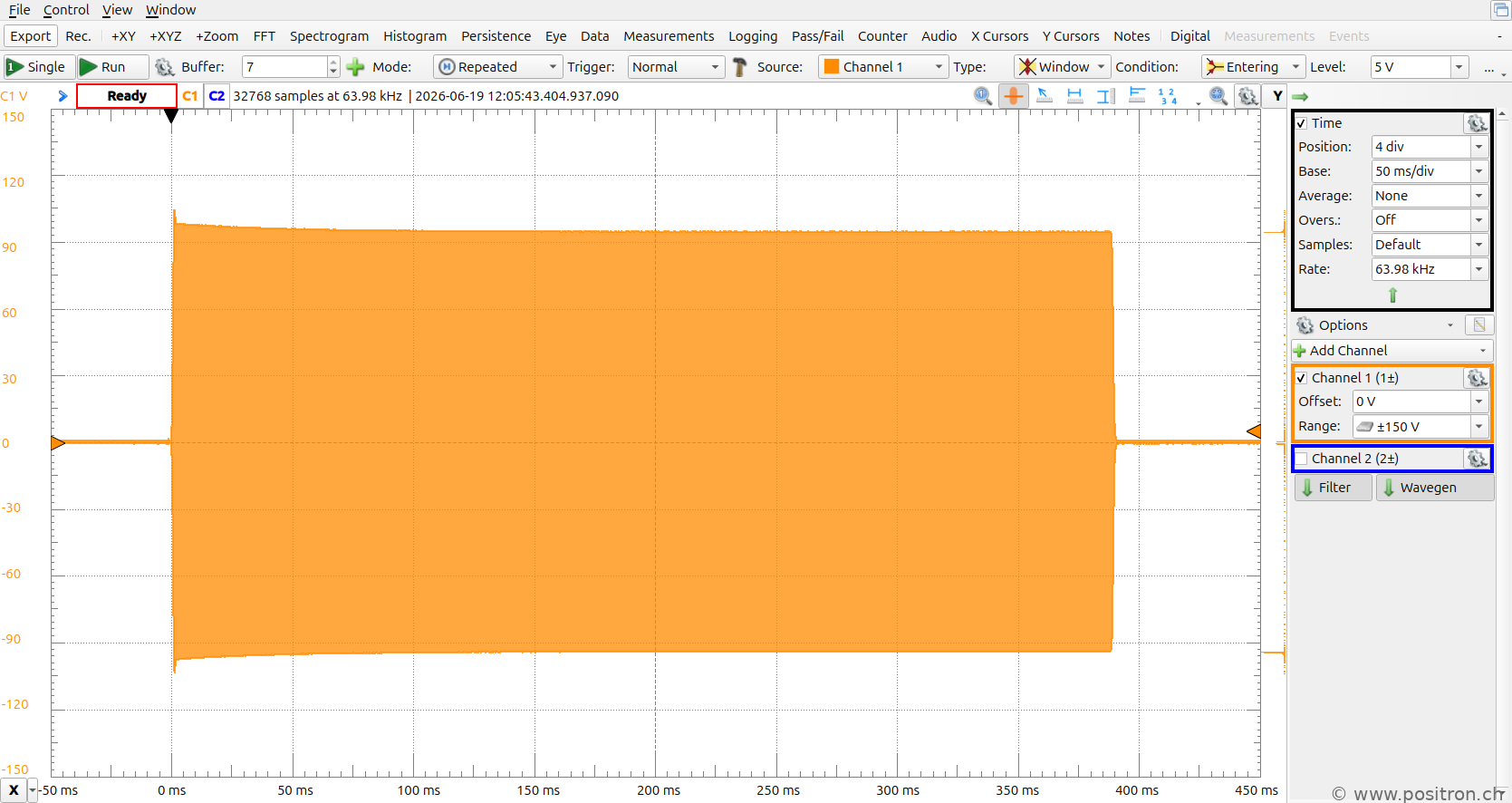
A longer time window, 5 W.
At 5 W into 50 Ω I expect 22.4 V peak. The voltage after the overshoot is approximately 28 V peak, corresponding to about 7.8 W. Over the next 100 ms the voltage settles to approximately 22 V — a power control loop is presumably taking effect. |
 |
|
A longer time window, 100 W. The overshoot and power settling are less pronounced. |
 |
| Waterfall of a KiwiSDR receiver showing my keyed signal at 100 W and 4 ms. A clearly broadened spectrum is visible during keying. | 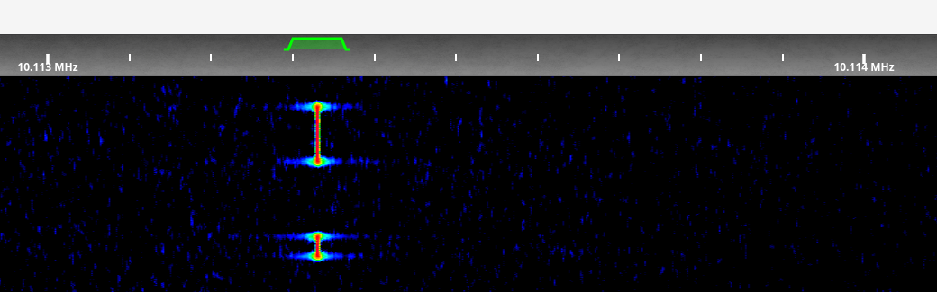 |
|
The FT-991A does not switch hard, but not particularly optimally either. The good intention is recognisable. There is room for improvement. |
|