Home
Antennas
ATAS-120A
> HLP 270
magnetic_loop
Various
Impressum
Sitemap
Printable version
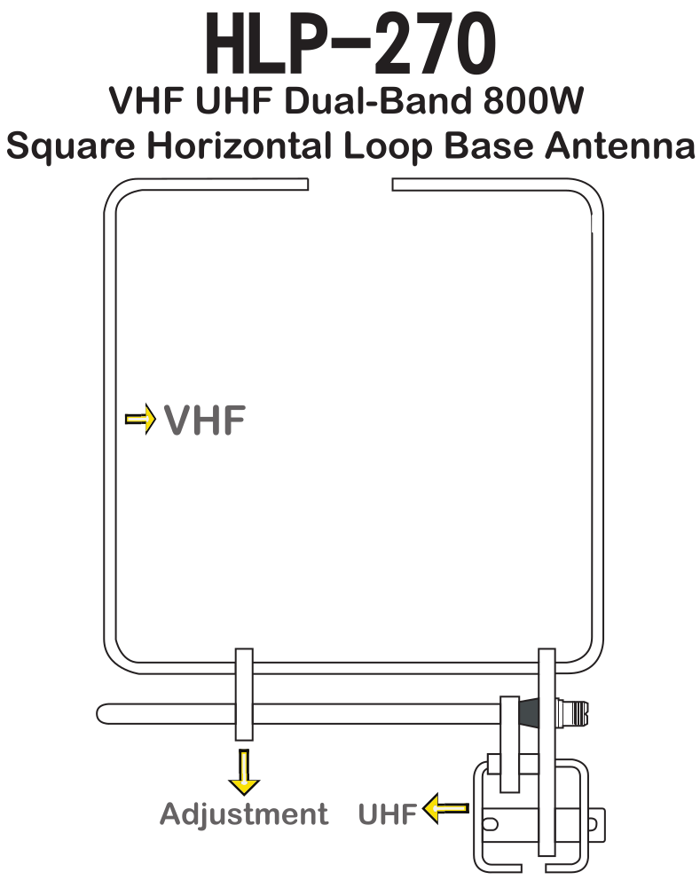
HLP 270 dualband 2m 70cm halo loop
|
I purchased a Sharman / Moonraker dualband halo loop. I took a closer look at it. |
|||||||||||||||||||||||
|
Image from advertisement. |
 |
||||||||||||||||||||||
|
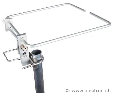
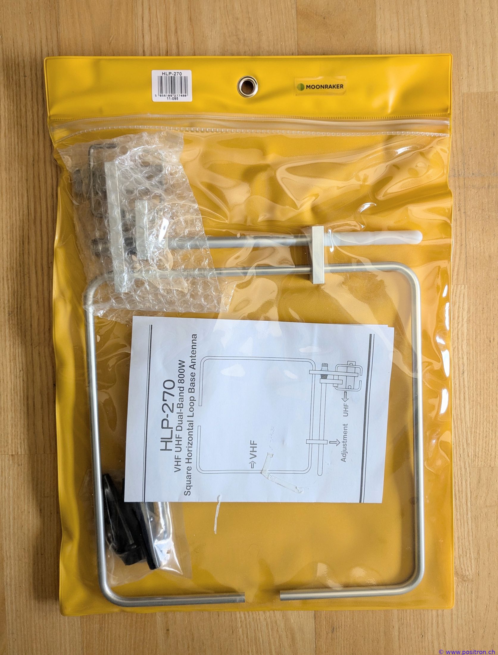
This is how the antenna is sold |
 |
||||||||||||||||||||||
|
Antenna assembled to minimum packing size. |
 |
||||||||||||||||||||||
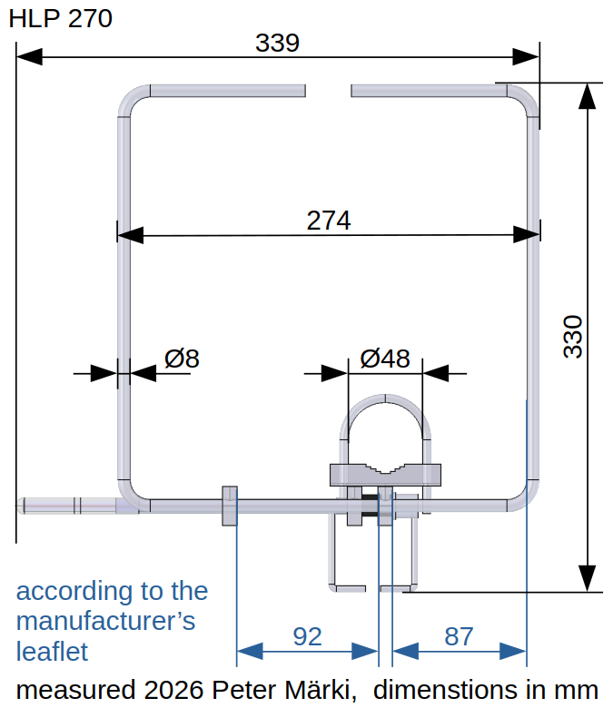
Outer dimensions |
|||||||||||||||||||||||
|
The leaflet describes how the antenna should be assembled. According to the leaflet, the antenna should have dimensions of 28 cm by 28 cm. The dimensions I measured are considerably larger. |
|
||||||||||||||||||||||
Leaflet |
|||||||||||||||||||||||
|
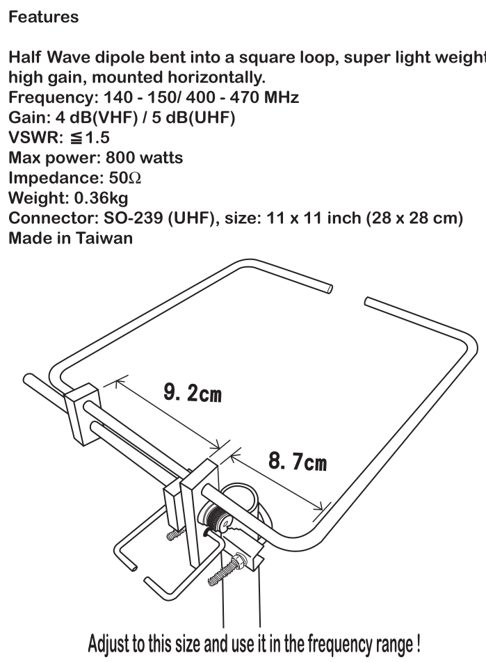
Manufacturer's leaflet page 1. |
 |
||||||||||||||||||||||
|
Manufacturer's leaflet page 2. |
 |
||||||||||||||||||||||
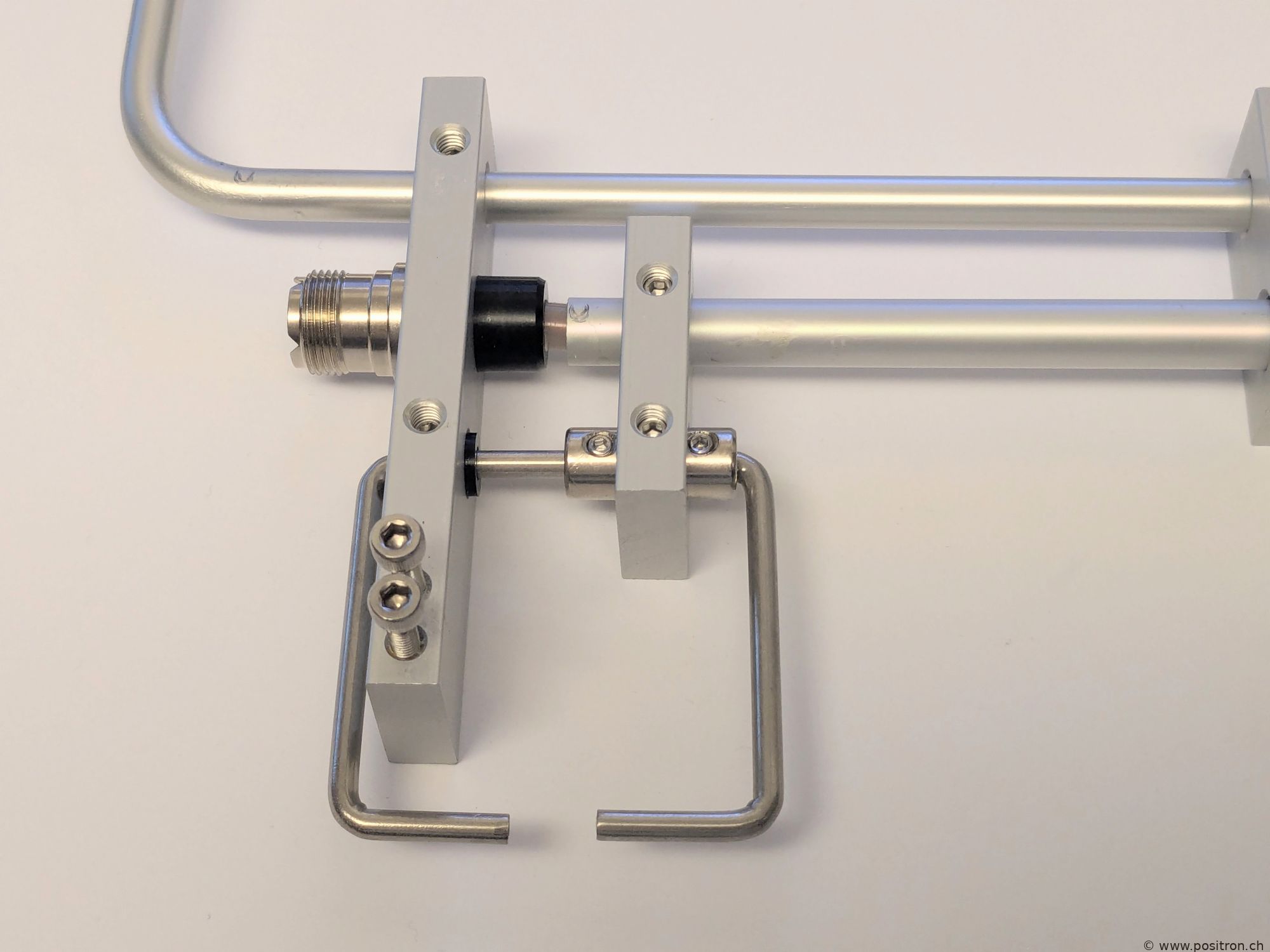
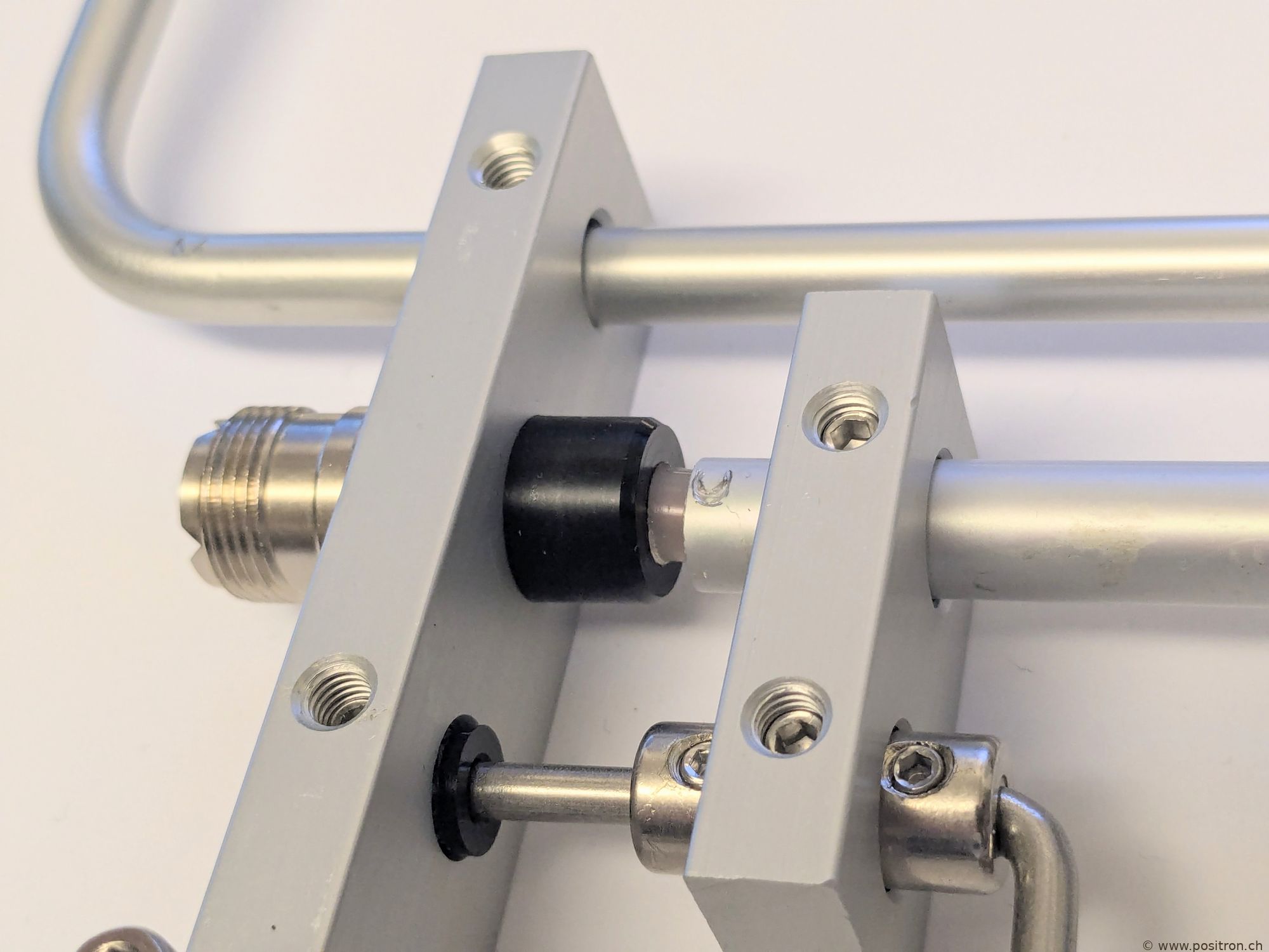
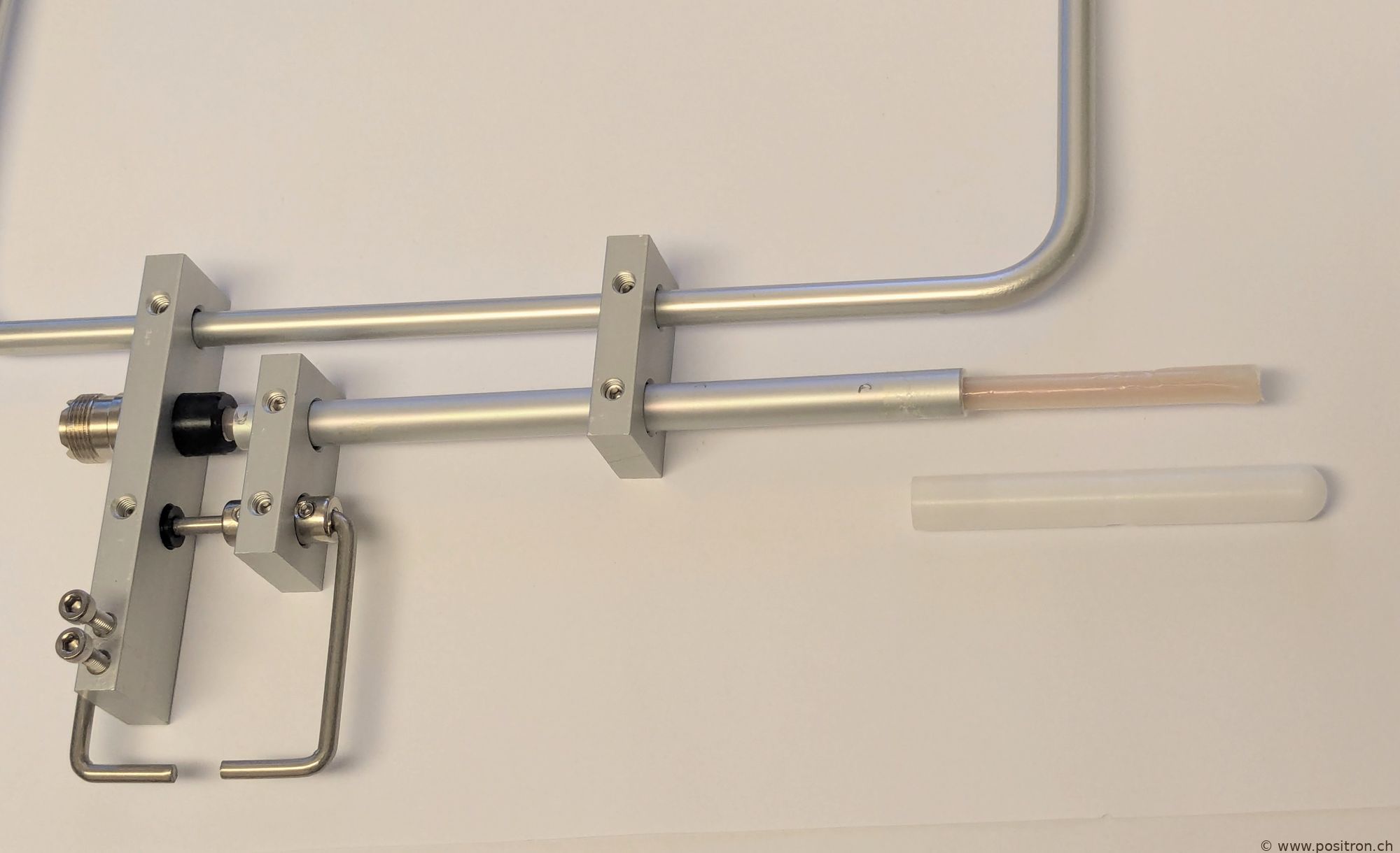
Photos |
|||||||||||||||||||||||
|
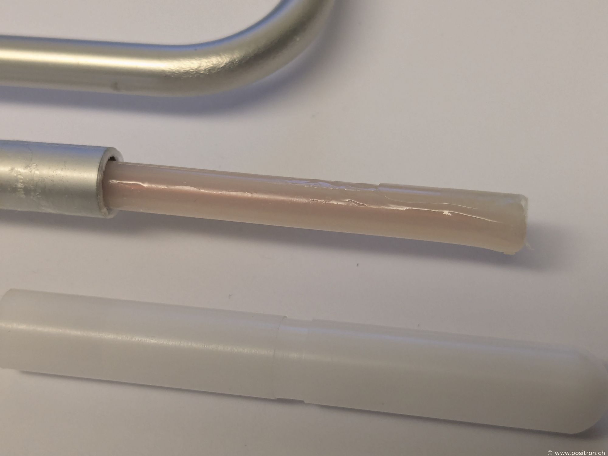
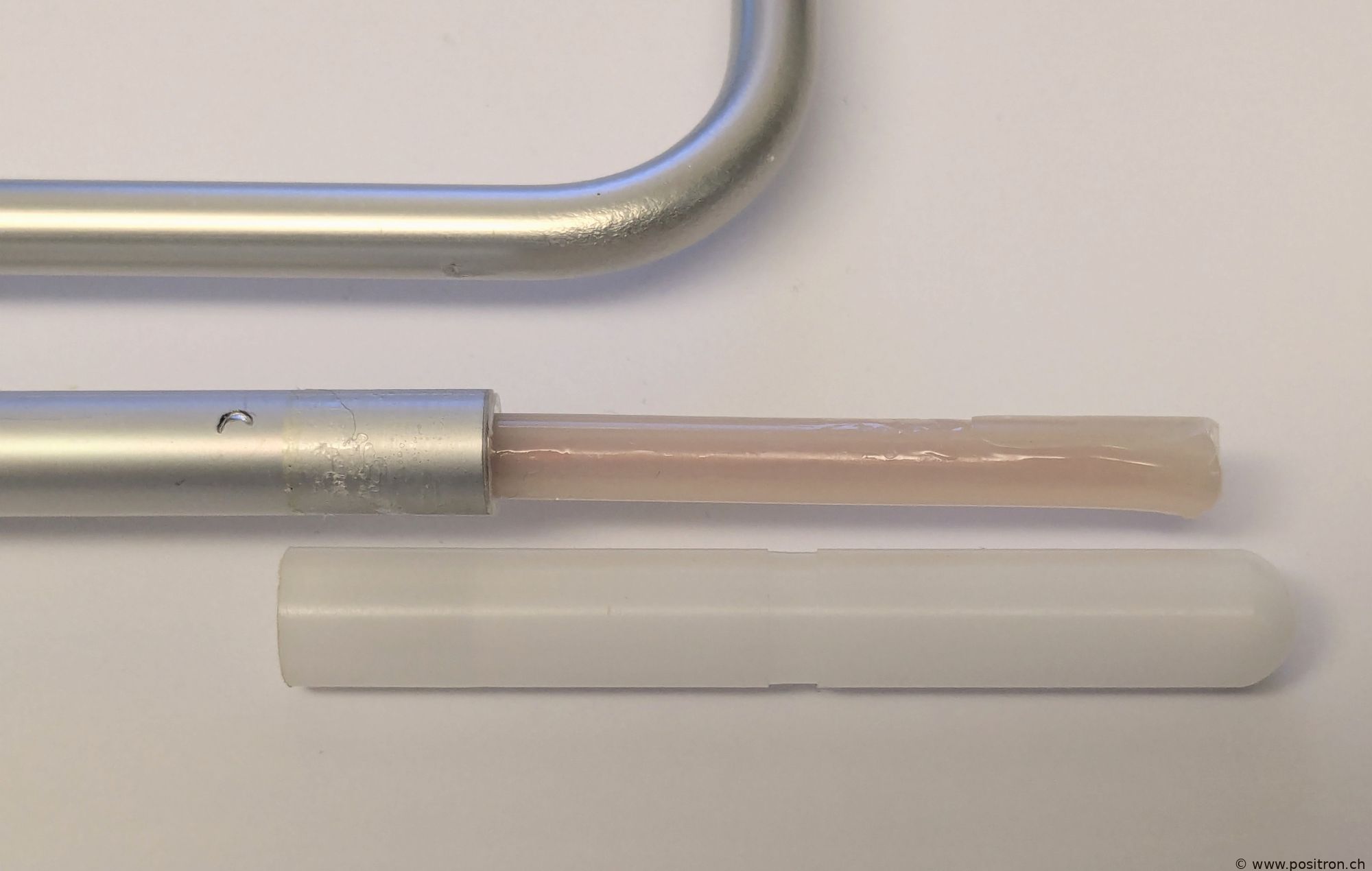
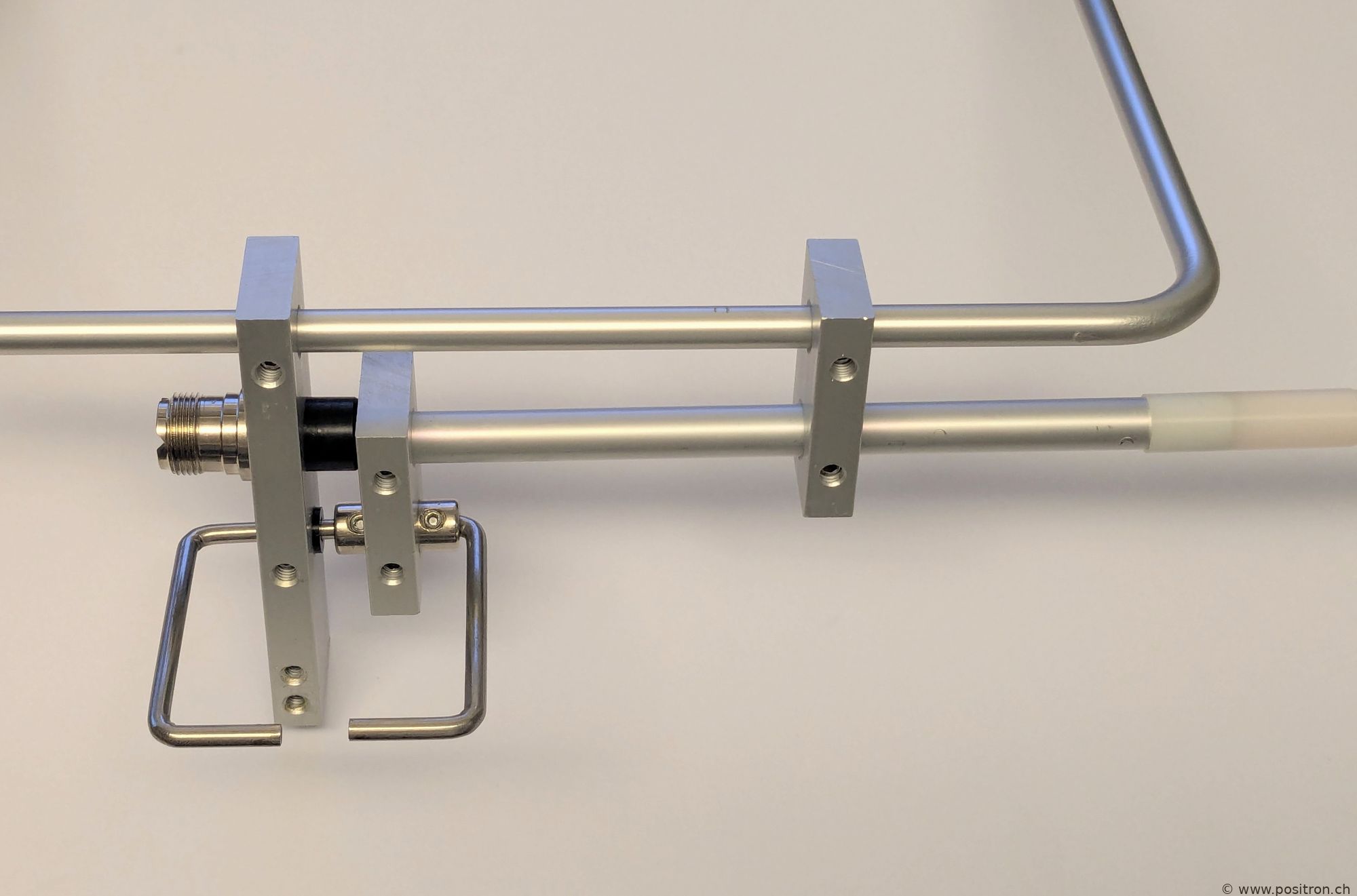
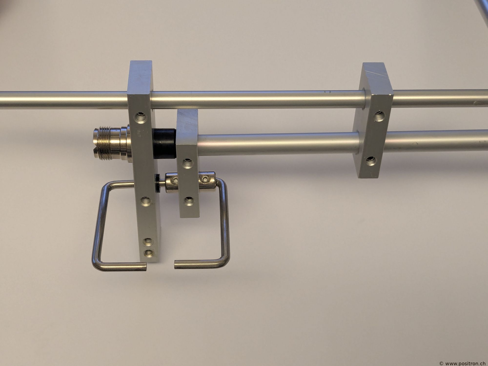
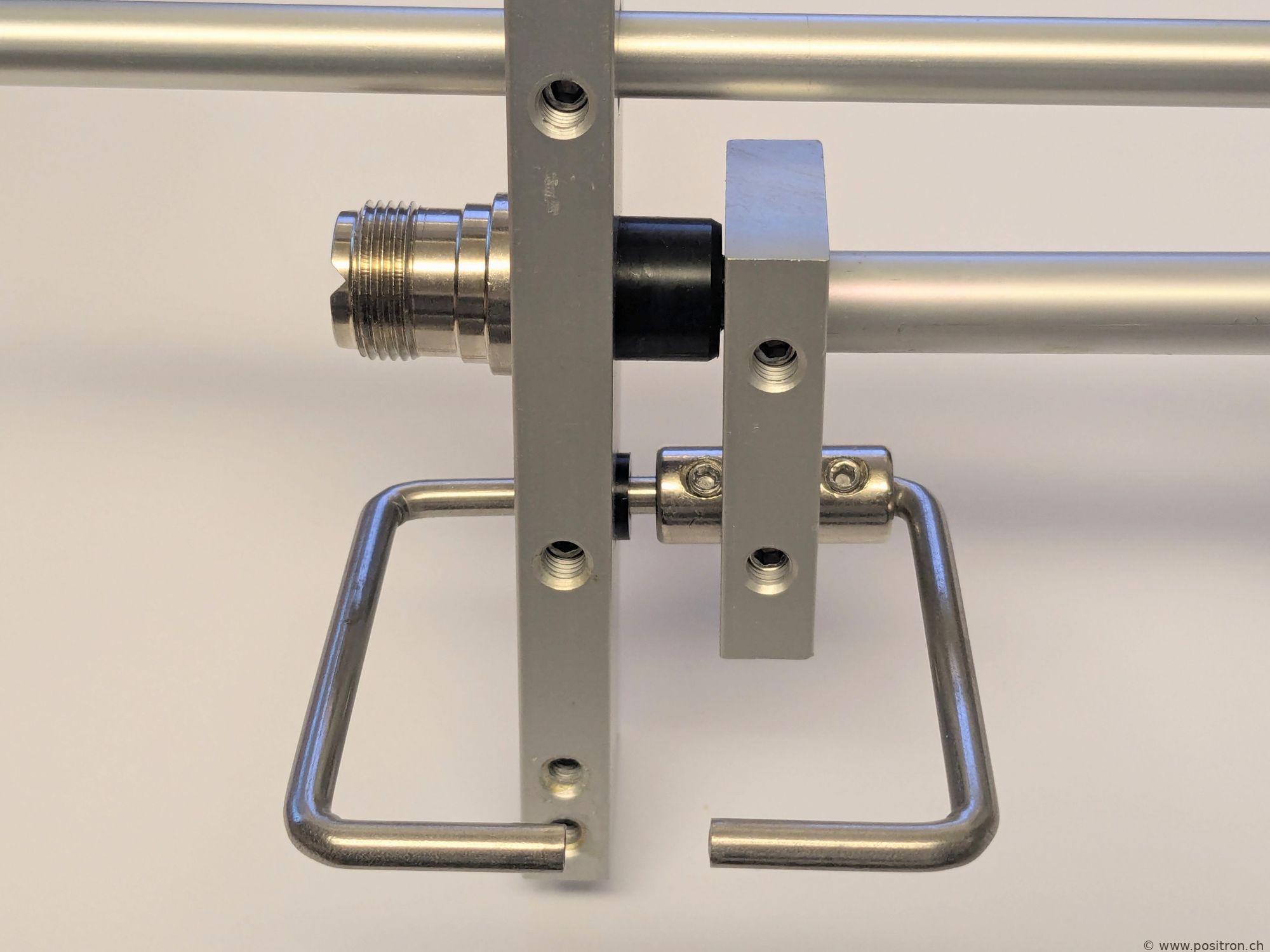
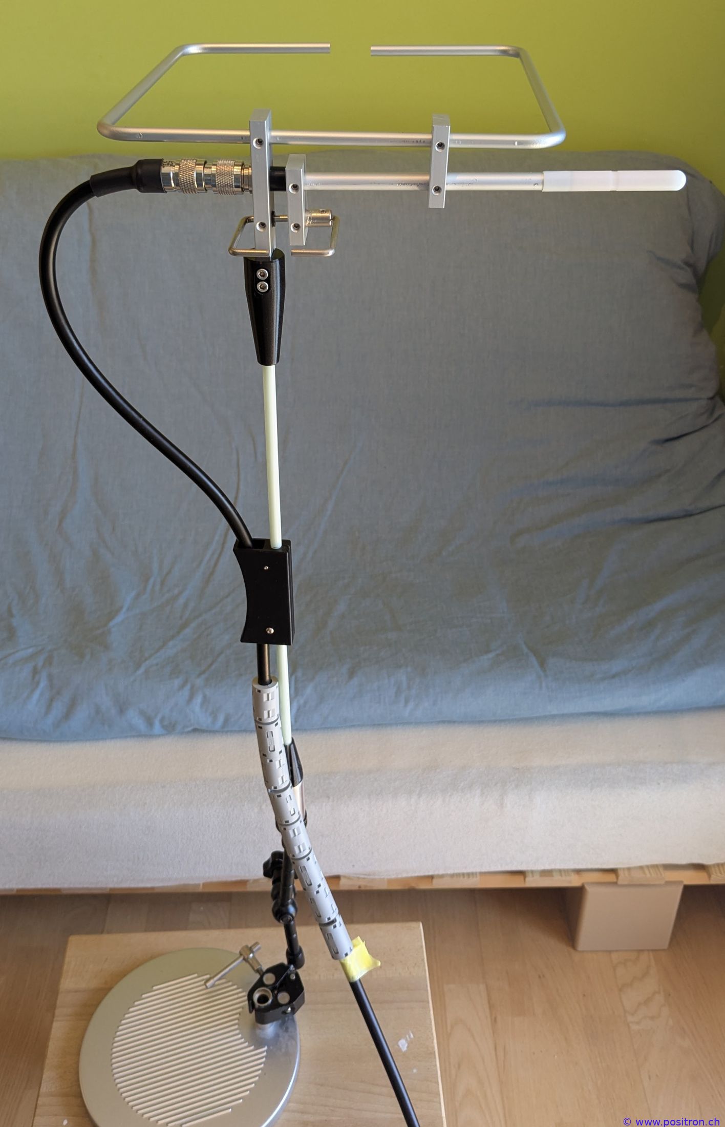
The second vertical bar was slightly shifted to the right. You can see the mark where the grub screw pressed against the aluminum tube. From the connector, an inner conductor with insulation runs through the aluminum tube. |
 |
||||||||||||||||||||||
|
Detail |
 |
||||||||||||||||||||||
|
On the right, the inner conductor with insulation comes out. I removed the white cover to make this more visible. |
 |
||||||||||||||||||||||
|
Odd shape because adhesive residue is still attached. |
 |
||||||||||||||||||||||
 |
|||||||||||||||||||||||
|
Bent according to the instructions |
 |
||||||||||||||||||||||
 |
|||||||||||||||||||||||
 |
|||||||||||||||||||||||
3D Model |
|||||||||||||||||||||||
|
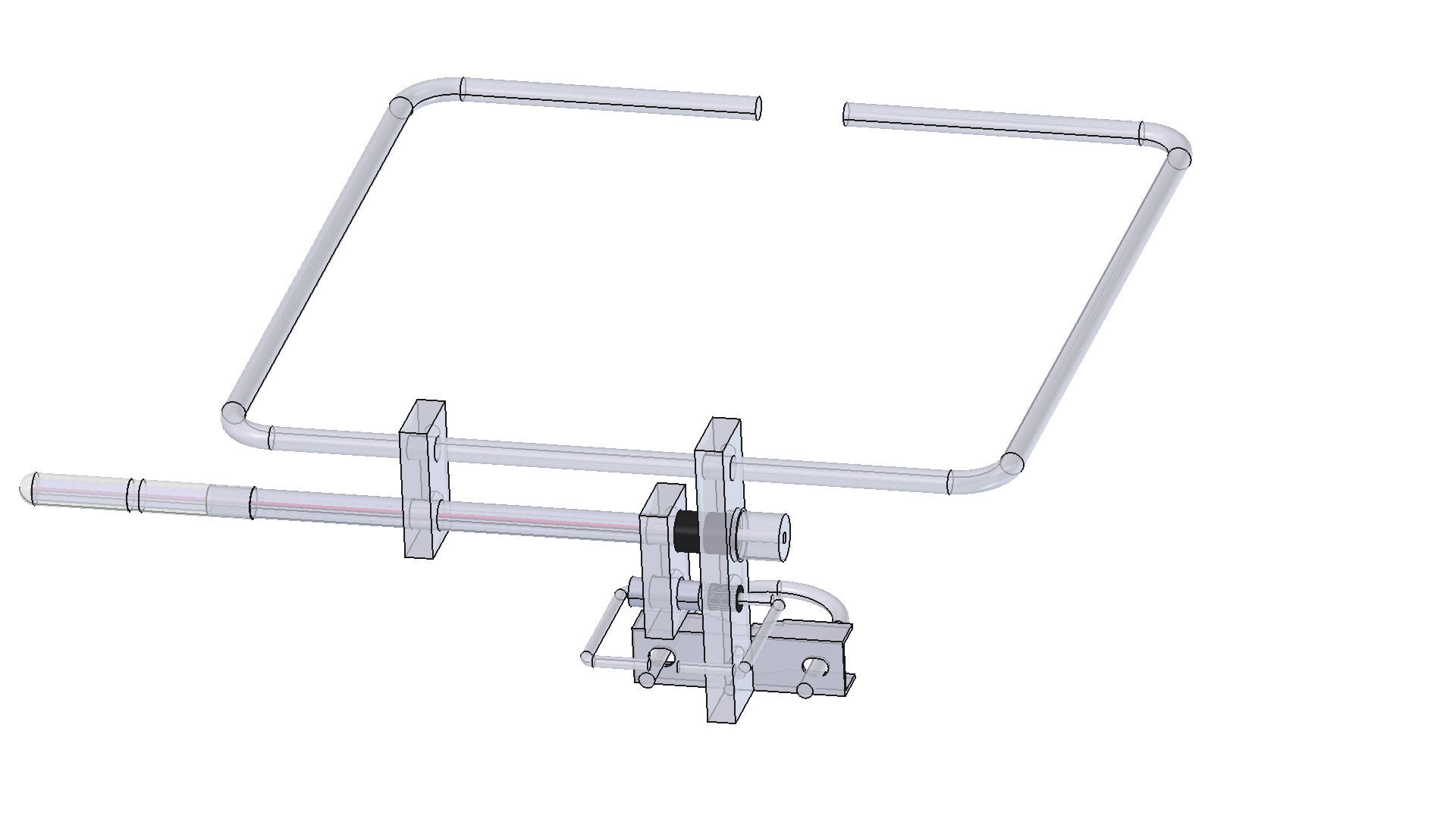
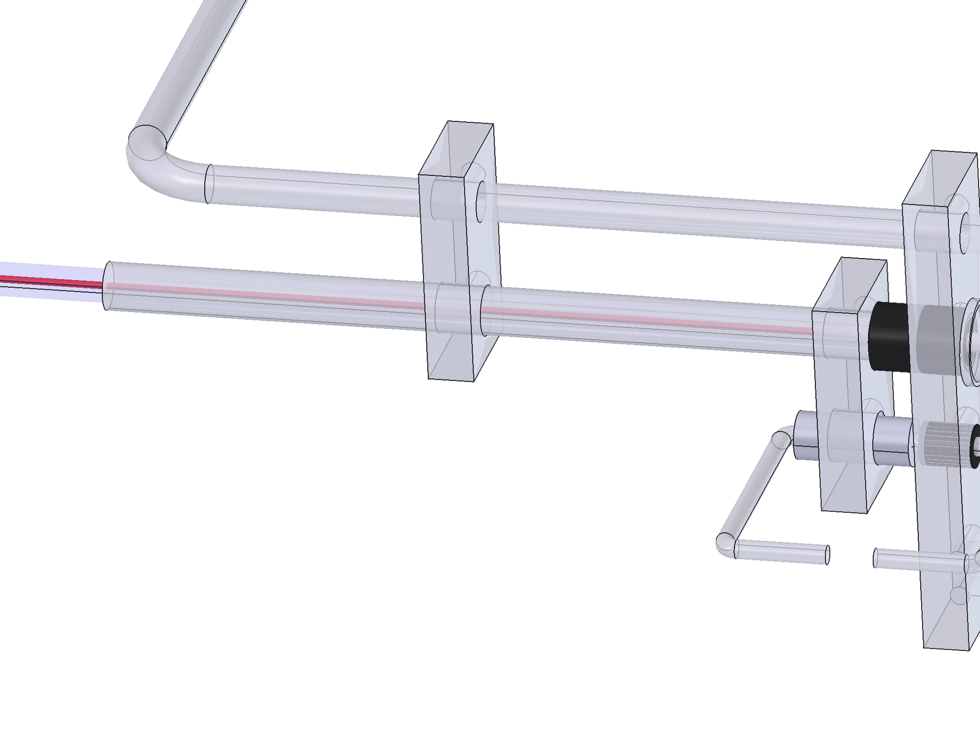
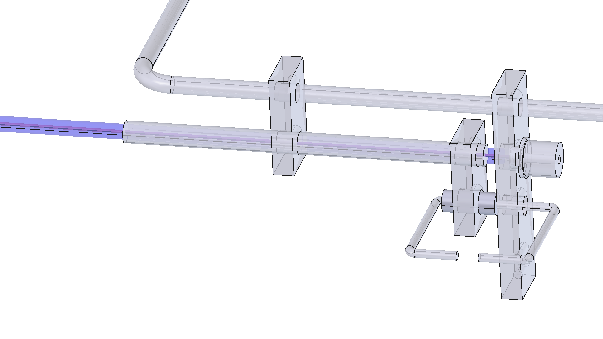
I created a 3D model. |
 |
||||||||||||||||||||||
|
White sheath removed. Inner conductor, red, visible. |
 |
||||||||||||||||||||||
|
All insulating sleeves and insulating parts removed. |
 |
||||||||||||||||||||||
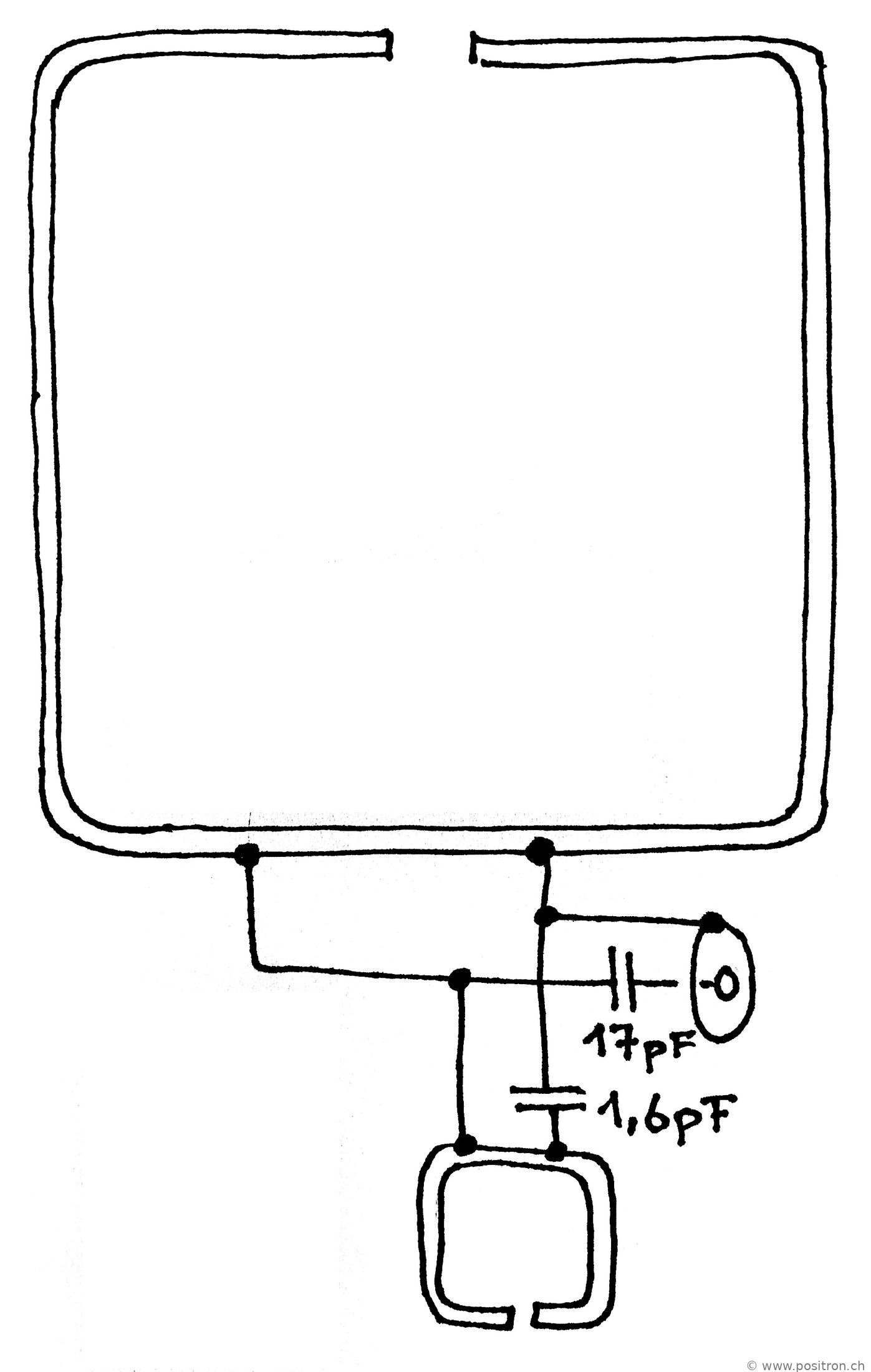
Abstracted schematic with partly lumped elements |
|||||||||||||||||||||||
|
For 2 meters, I recognize a classic gamma match with a series capacitance of 17 pF. |
 |
||||||||||||||||||||||
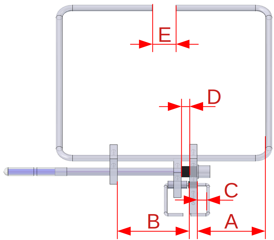
Designation of the dimensions |
|||||||||||||||||||||||
|
I vary the dimensions shown here. |
 |
||||||||||||||||||||||
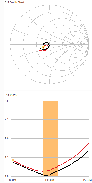
First overview measurement |
|||||||||||||||||||||||
|
For a first overview measurement, I used a 30 cm RG400 cable without a common-mode choke. This cable piece is
part of the measurement, the longer feed cable was included in the VNA calibration. |
|
||||||||||||||||||||||
|
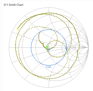
The Smith chart is still quite confusing over the large frequency range from 100 MHz to 500 MHz. |
|
||||||||||||||||||||||
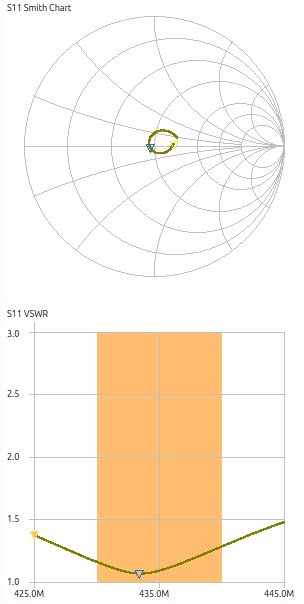
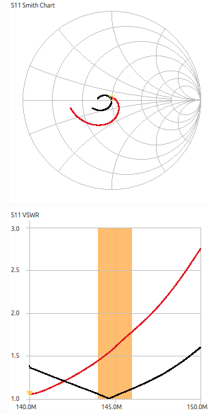
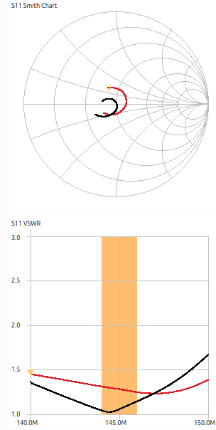
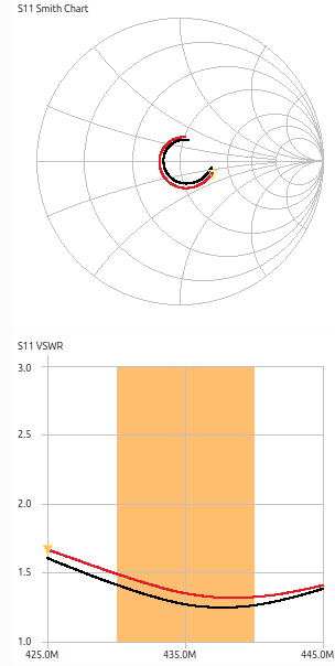
| SWR 2m and 70cm bands highlighted in grey. Fits quite nicely. | 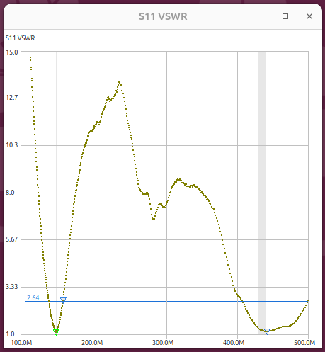
|
||||||||||||||||||||||
Calibration of the network analyzer |
|||||||||||||||||||||||
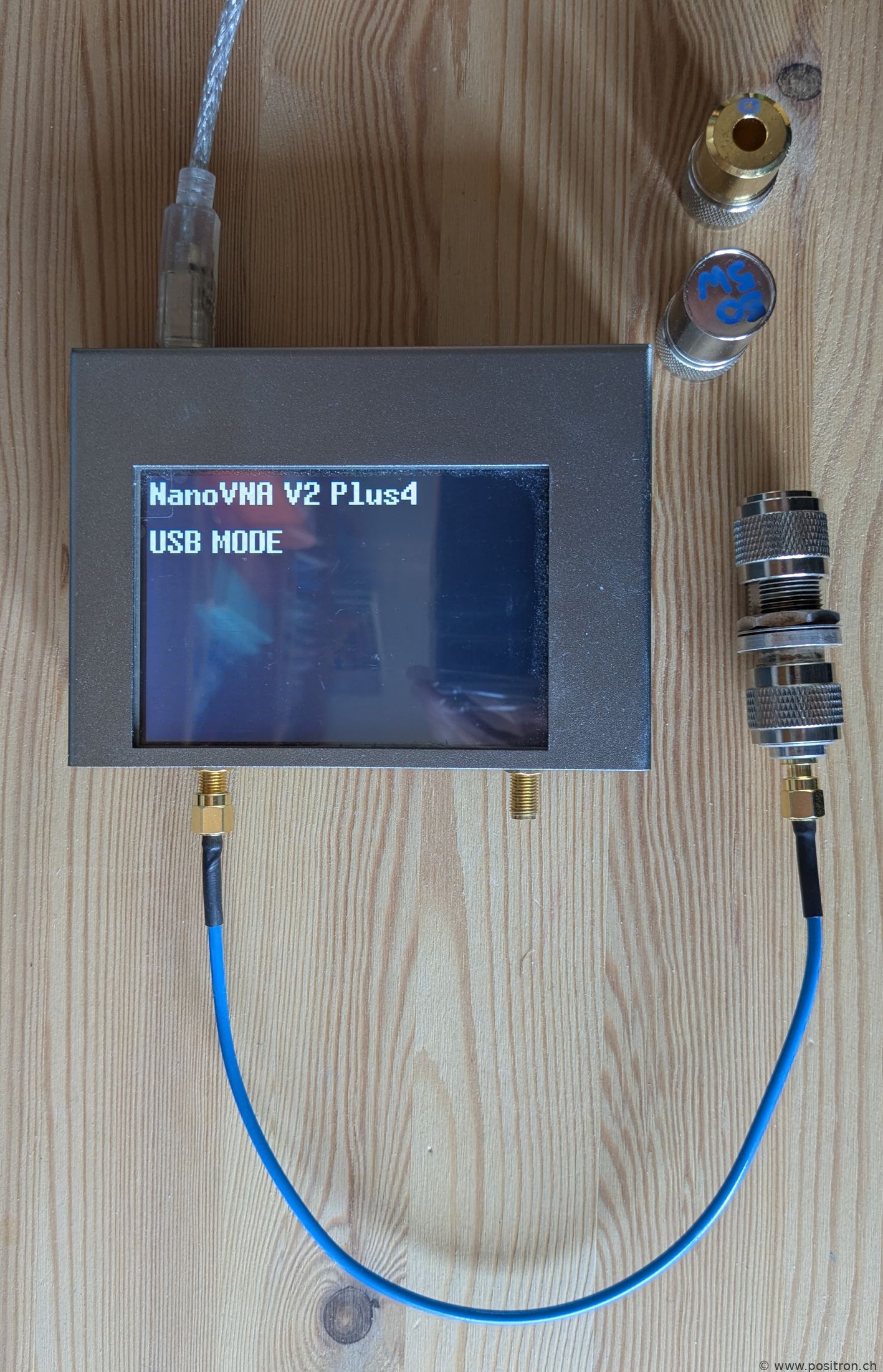
|
I calibrate the VNA directly at the VNA using N-type references.
The antenna is then connected with a 2m LMR400 cable. This cable is therefore considered part of the antenna. |
 |
||||||||||||||||||||||
Without common-mode choke |
|||||||||||||||||||||||
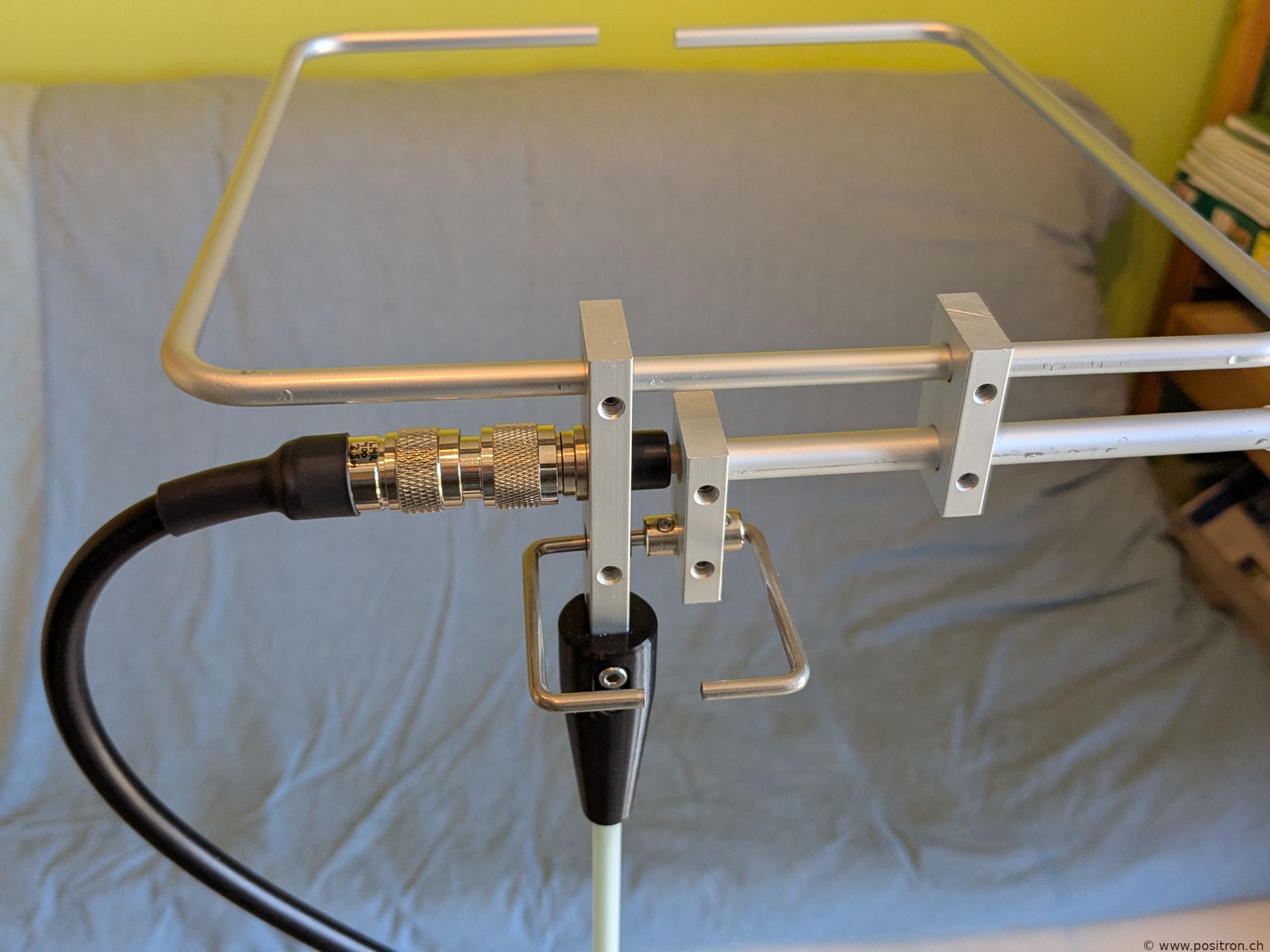
| Note: I mounted the antenna mirrored because I want to route the cable from the left to the antenna. This mirroring should have no influence though. | 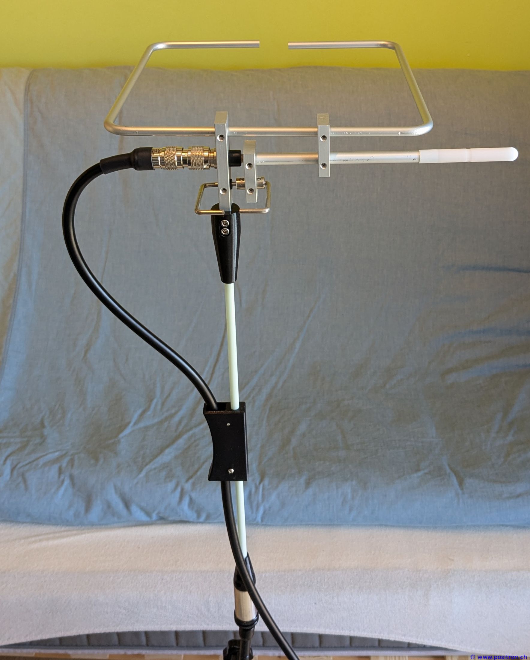 |
||||||||||||||||||||||
|
 |
||||||||||||||||||||||
|
|||||||||||||||||||||||
|
|||||||||||||||||||||||
10 ferrite clamps too close to the antenna, severely detuned |
|||||||||||||||||||||||
|
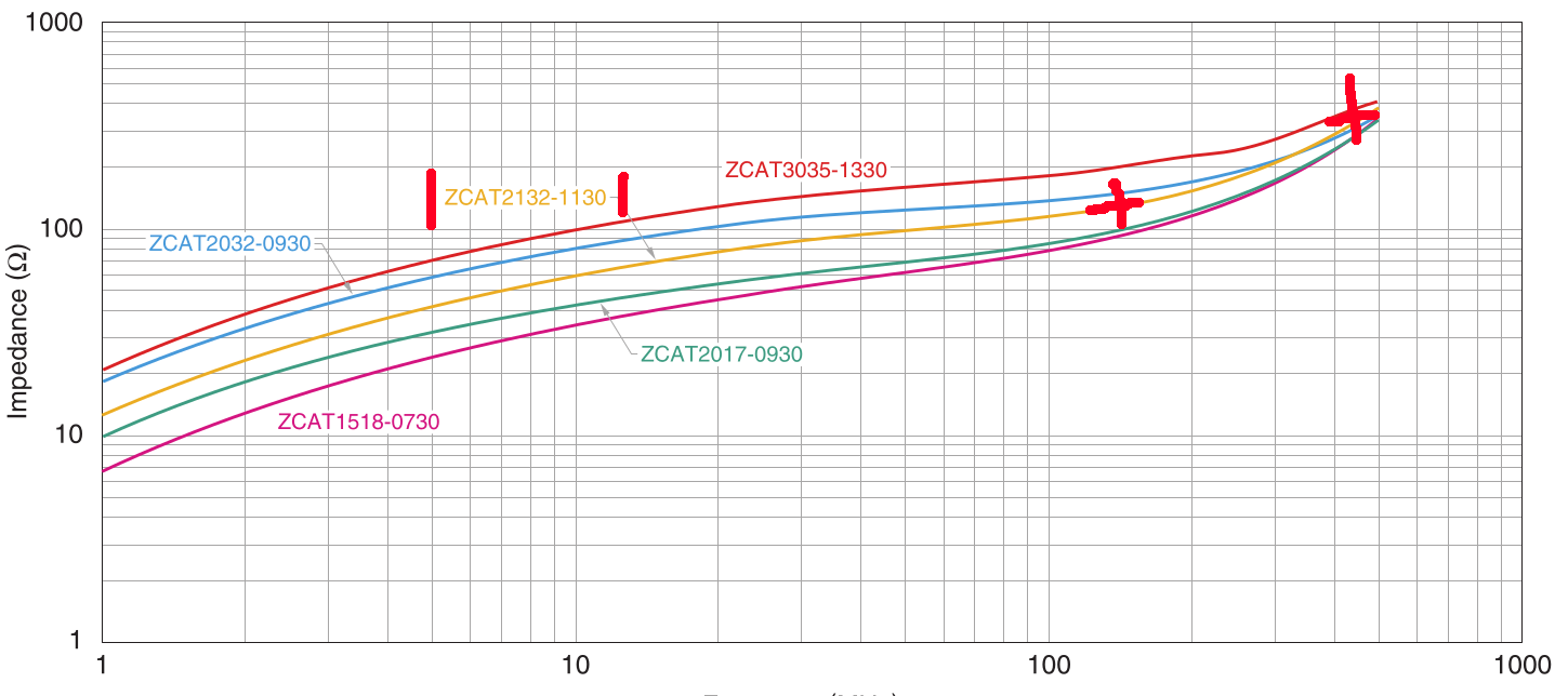
10 ferrite clamps of type ZCAT2132-1130 mounted on the cable.
per ferrite this gives an impedance of approximately 120 Ohm at 2m and 350 Ohm at 70 cm. |
 |
||||||||||||||||||||||
| The ferrites are relatively close to the antenna. | 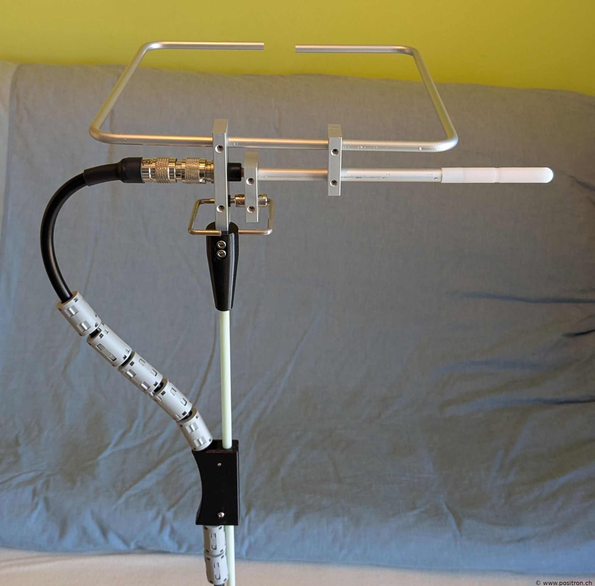 |
||||||||||||||||||||||
| 2m band: the resonance is severely too low. | 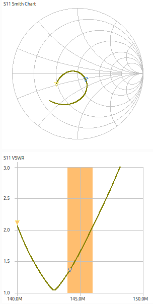
|
||||||||||||||||||||||
|
70 cm: the resonance is severely too high.
The ferrites have a large influence. Findings: the cable is part of the antenna. The ferrites are too close and I cannot tune the antenna this way. In my setup I have a non-conductive GRP mast. A conductive mast would likely affect things differently. |
|
||||||||||||||||||||||
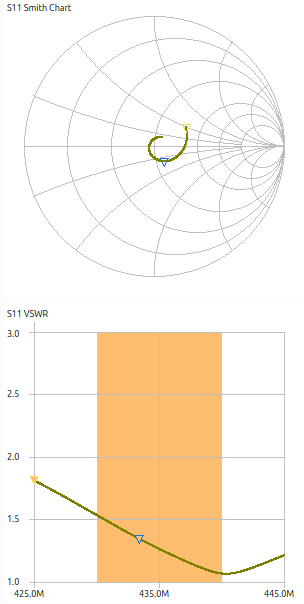
Common-mode choke further down the cable, good setting found |
|||||||||||||||||||||||
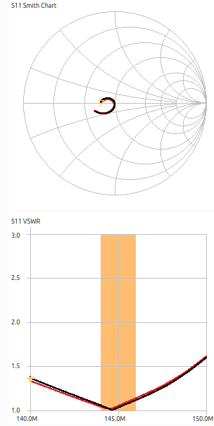
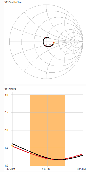
With this setting the result is satisfactory. In both bands the SWR is below 1.5 as promised in the datasheet. |
 |
||||||||||||||||||||||
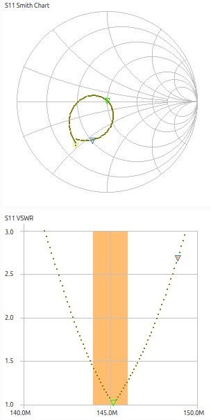
| 2m band looks very good. | 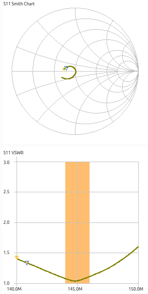
|
||||||||||||||||||||||
| 70 cm band satisfactory. | 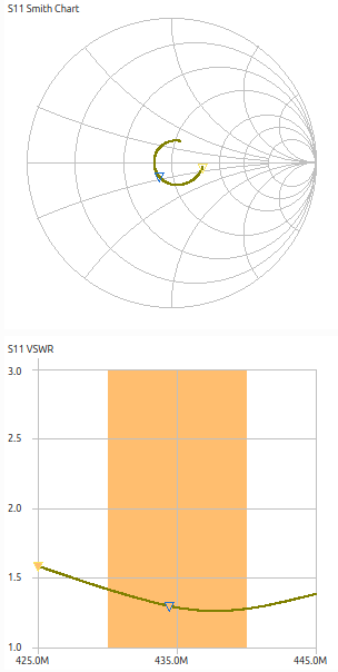
|
||||||||||||||||||||||
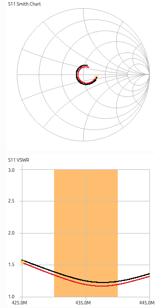
Influence of the choke position |
|||||||||||||||||||||||
| The chain of chokes is moved 25 mm higher using yellow tape. | 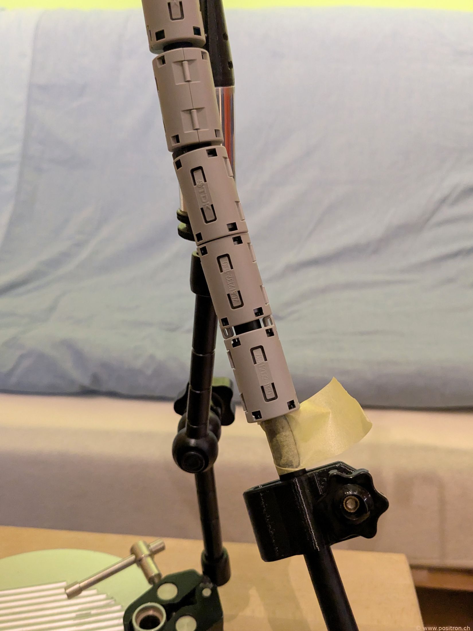
|
||||||||||||||||||||||
|
Black: original position. Red: chokes 25 mm higher.
Remarkable: even this small change shifts the resonance frequency massively lower. |

|
||||||||||||||||||||||
| Black: original position. Red: chokes 25 mm higher. | 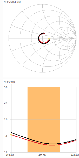
|
||||||||||||||||||||||
Influence of copper sheet on side of cable |
|||||||||||||||||||||||
| A copper sheet 43 mm by 38 mm is attached to the side of the cable. | 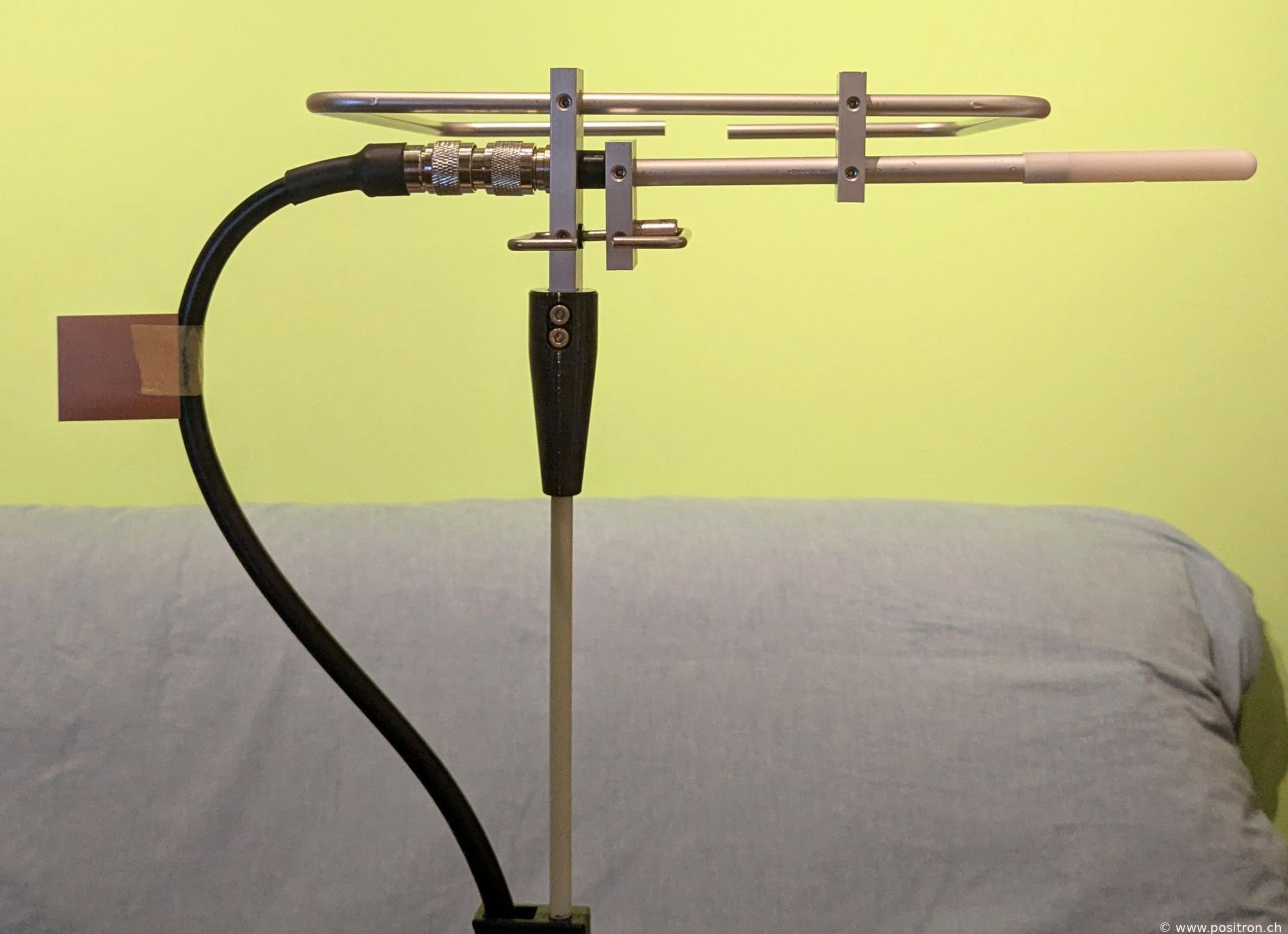
|
||||||||||||||||||||||
|
Black: reference, red: with copper sheet.
Influence clearly visible. |

|
||||||||||||||||||||||
|
Black: reference, red: with copper sheet.
Influence minor. |
|
||||||||||||||||||||||
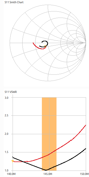
Influence of copper sheet on large loop, left side |
|||||||||||||||||||||||
| Copper sheet 43 mm by 38 mm on the left of the loop. | 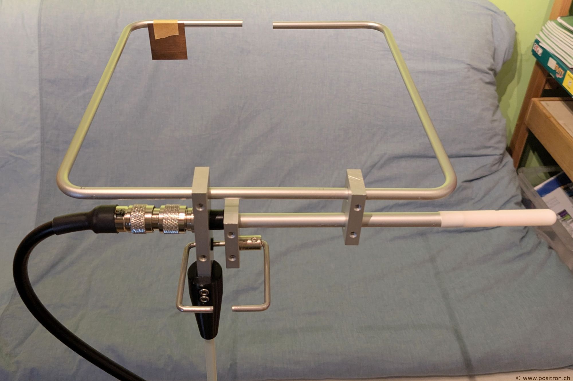
|
||||||||||||||||||||||
|
Black: reference, red: with copper sheet.
The influence is significant at 2m. |
|
||||||||||||||||||||||
| Black: reference, red: with copper sheet. | 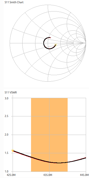
|
||||||||||||||||||||||
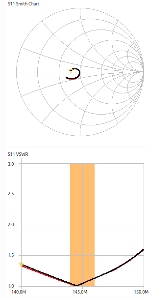
| Copper sheet on the right of the loop. | 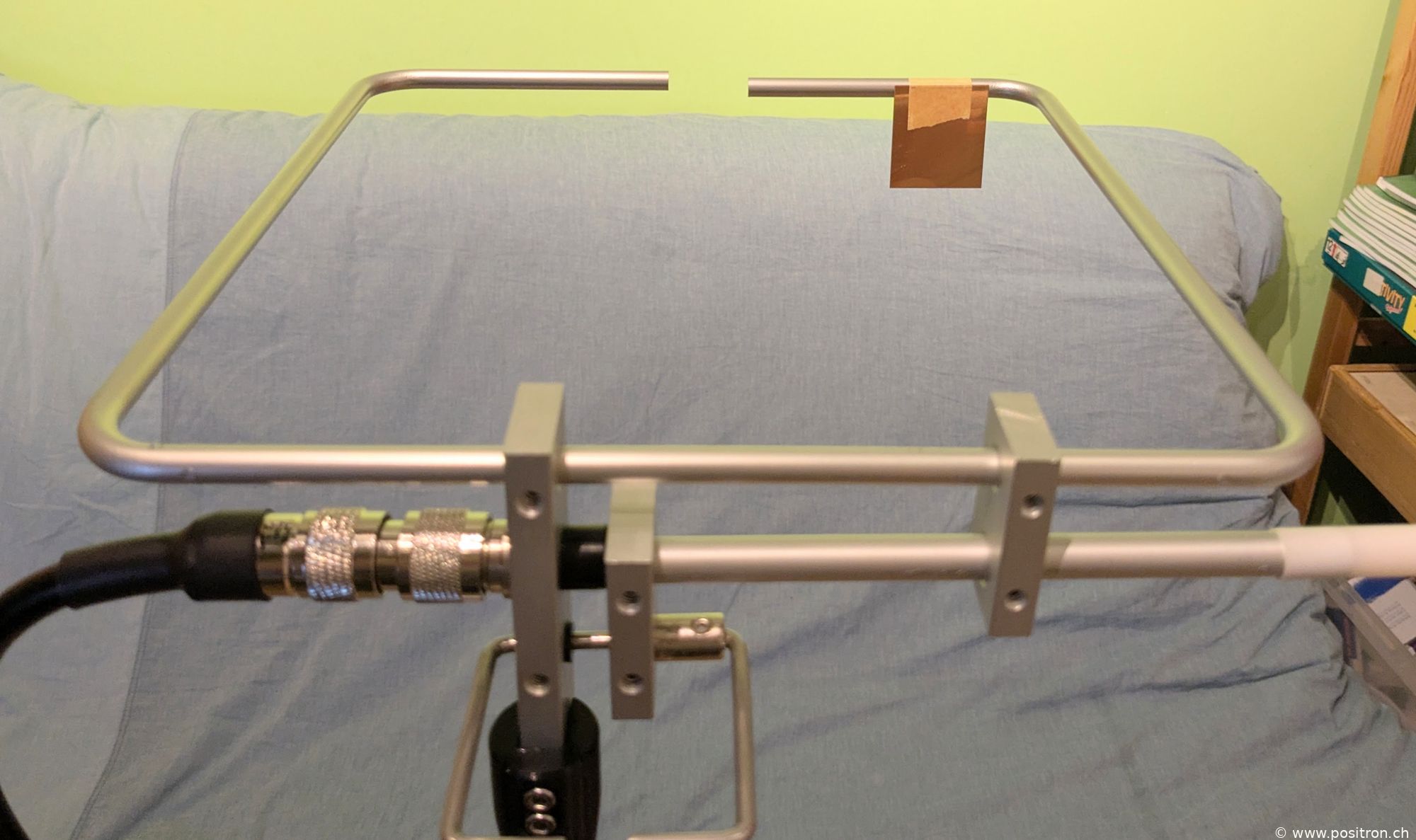
|
||||||||||||||||||||||
|
Black: reference, red: with copper sheet.
The influence is significant at 2m. |
|
||||||||||||||||||||||
|
Black: reference, red: with copper sheet.
Almost no influence. |
|
||||||||||||||||||||||
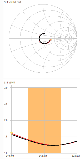
| Copper sheet 43 mm by 38 mm at the gamma match. | 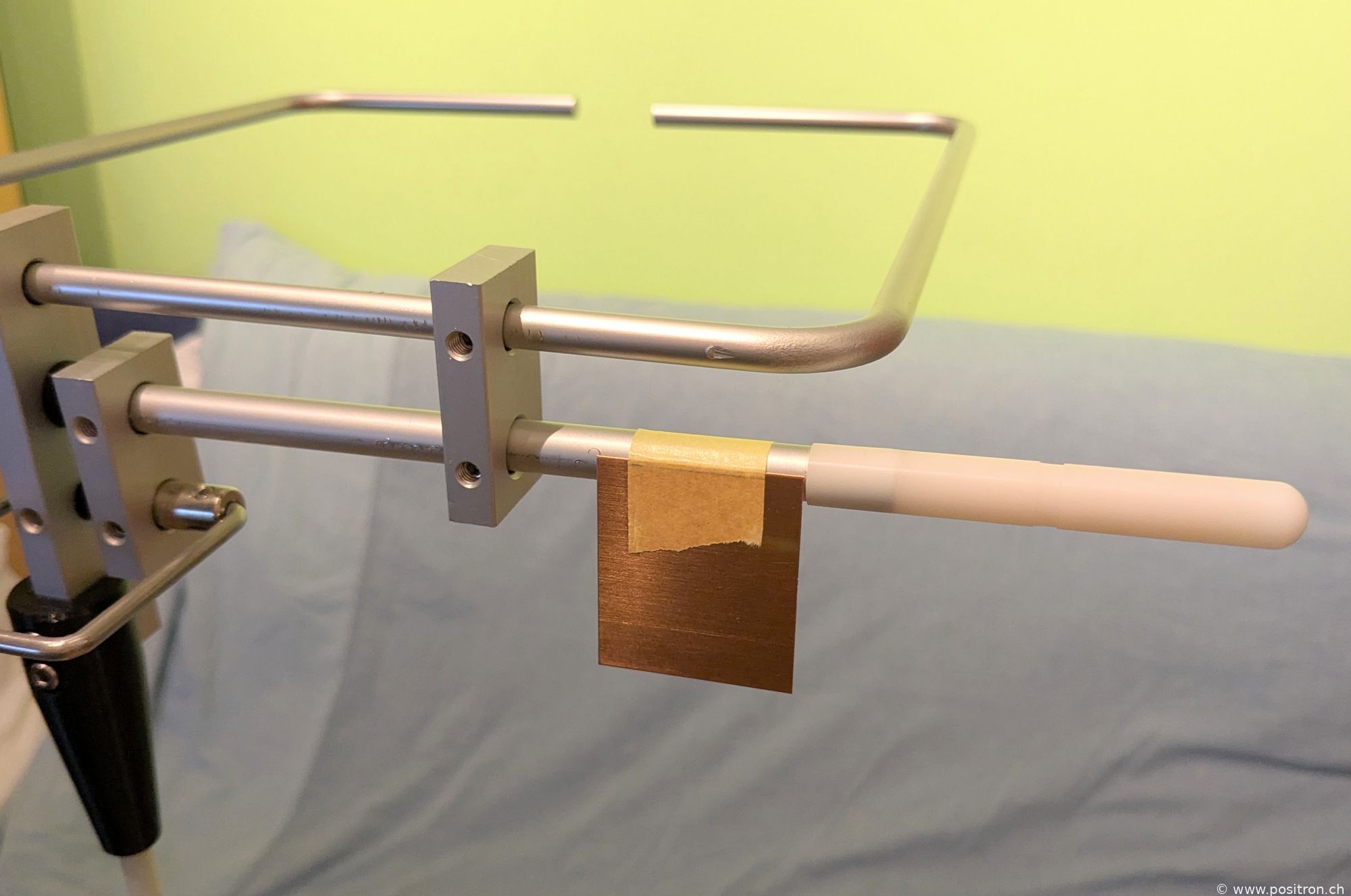
|
||||||||||||||||||||||
|
Black: reference, red: with copper sheet.
No influence. |
|
||||||||||||||||||||||
| Black: reference, red: with copper sheet. | 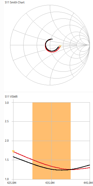
|
||||||||||||||||||||||
Influence of copper sheet on the small loop |
|||||||||||||||||||||||
| Copper sheet 44 mm by 21 mm on the small loop. | 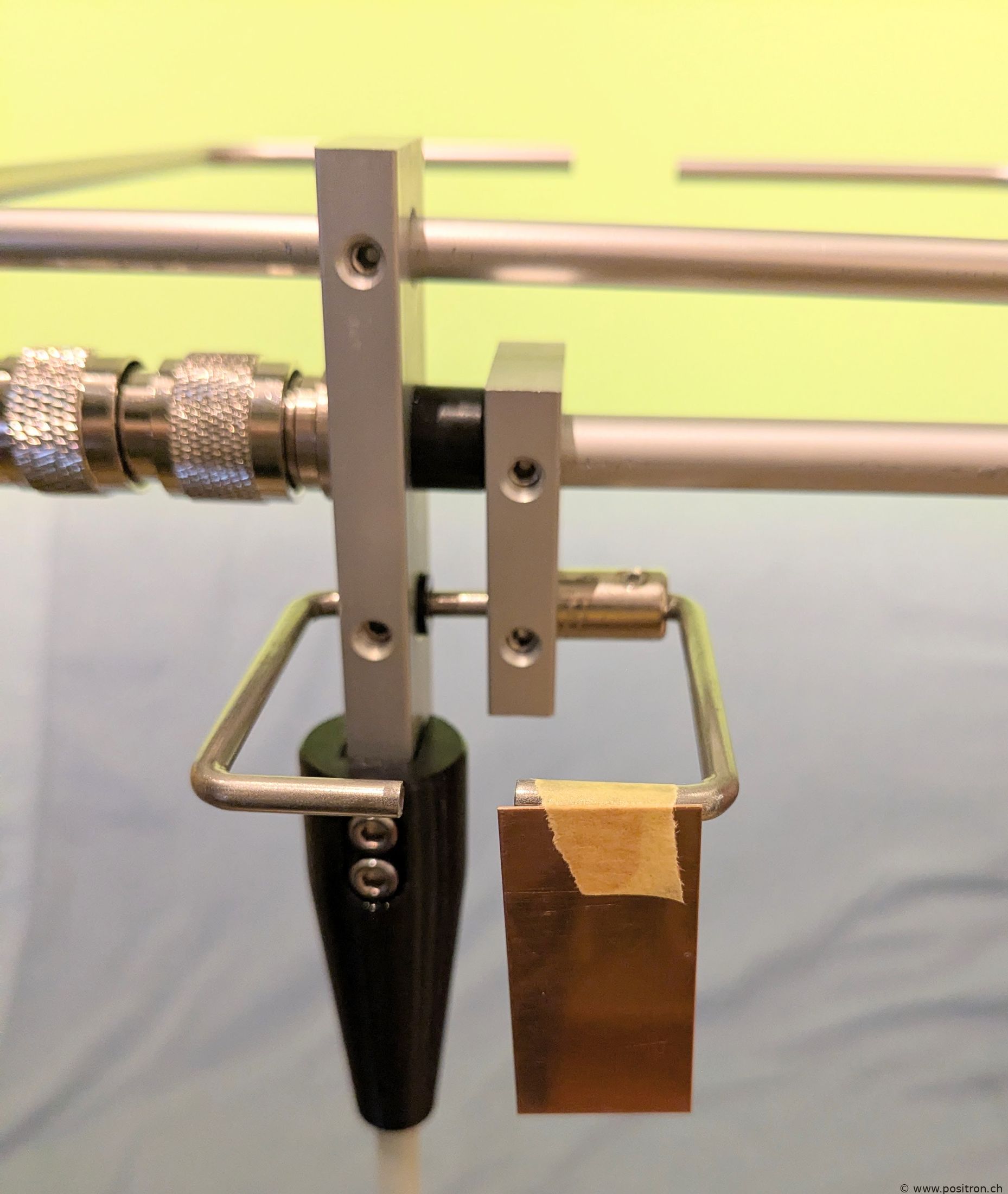
|
||||||||||||||||||||||
|
Black: reference, red: with copper sheet.
No influence. |

|
||||||||||||||||||||||
|
Black: reference, red: with copper sheet.
No influence. I would have expected the small loop to have a strong effect at 70 cm and I am surprised to see no influence here. Is the small loop merely decorative? |

|
||||||||||||||||||||||
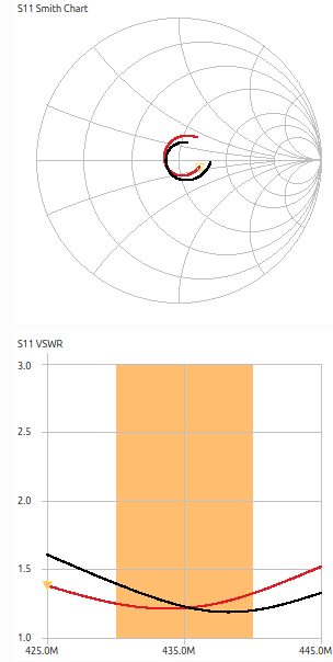
Influence of dimension A |
|||||||||||||||||||||||
| Dimension A. | 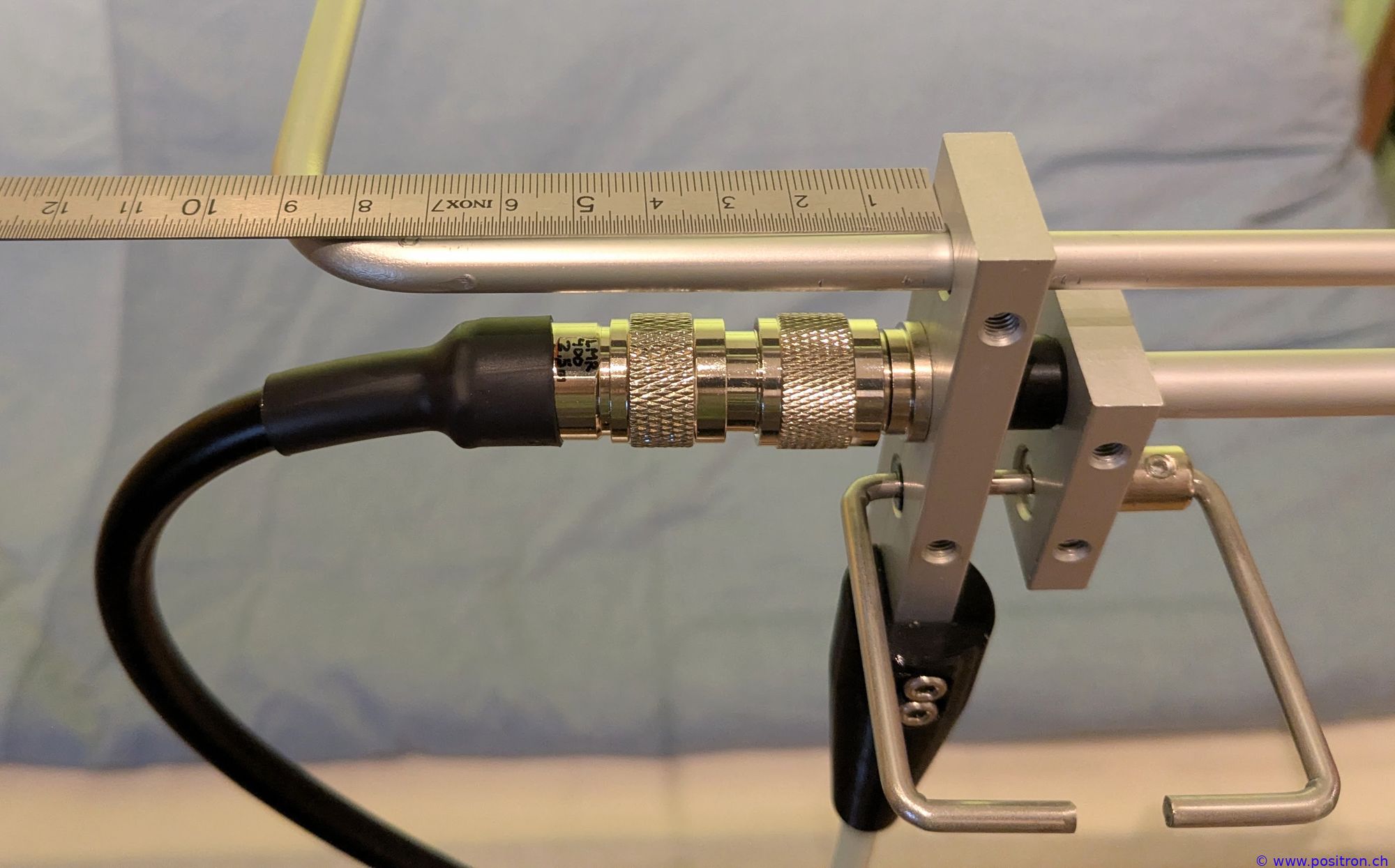
|
||||||||||||||||||||||
|
Black: A=87 mm Red: 10 mm larger: A=97 mm |

|
||||||||||||||||||||||
|
Black: original A=87 mm Red: 10 mm larger: A=97 mm |
|
||||||||||||||||||||||
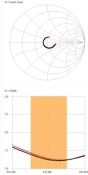
Influence of dimension B |
|||||||||||||||||||||||
| Dimension B = 92 mm. | 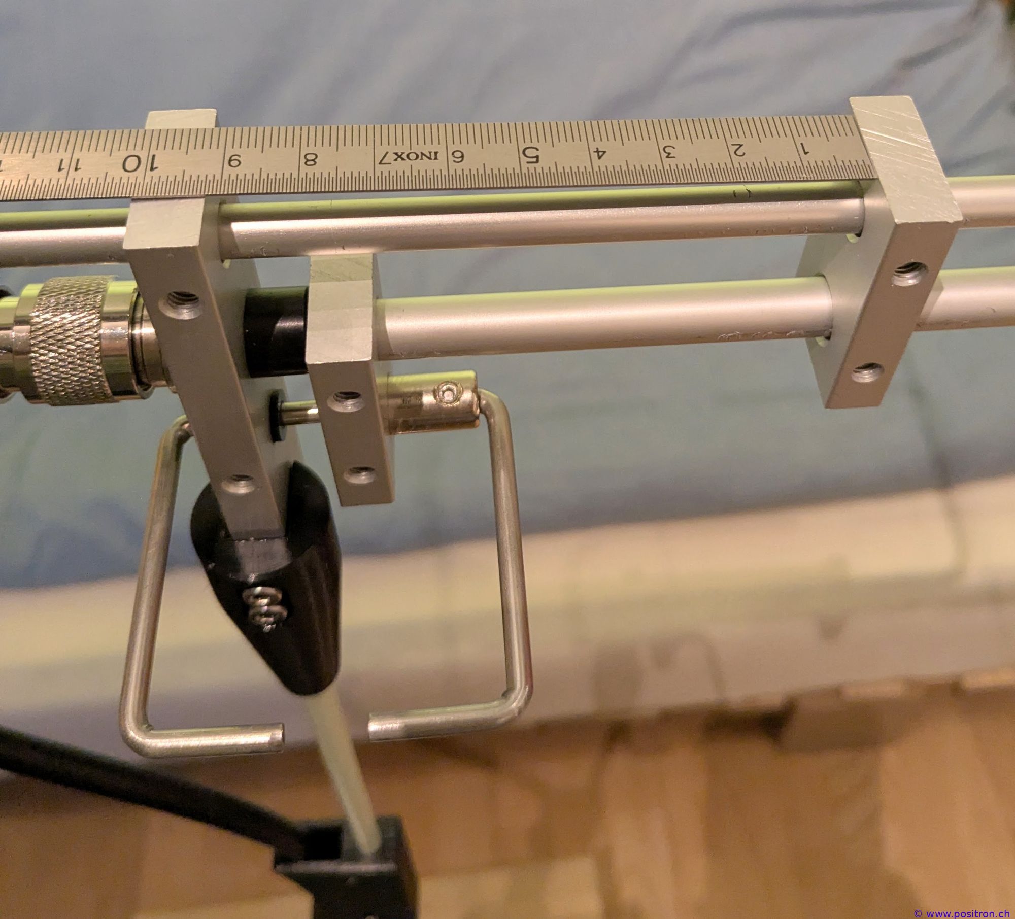
|
||||||||||||||||||||||
|
Black: B=92 mm Red: B=102 mm Smith chart: the circle gets larger, the coupling increases – as expected. |
|
||||||||||||||||||||||
|
Black: B=92 mm Red: B=102 mm Smith chart: the circle gets larger, the coupling increases – as expected. |
|
||||||||||||||||||||||
Influence of dimension C |
|||||||||||||||||||||||
| Dimension C = 8 mm. | 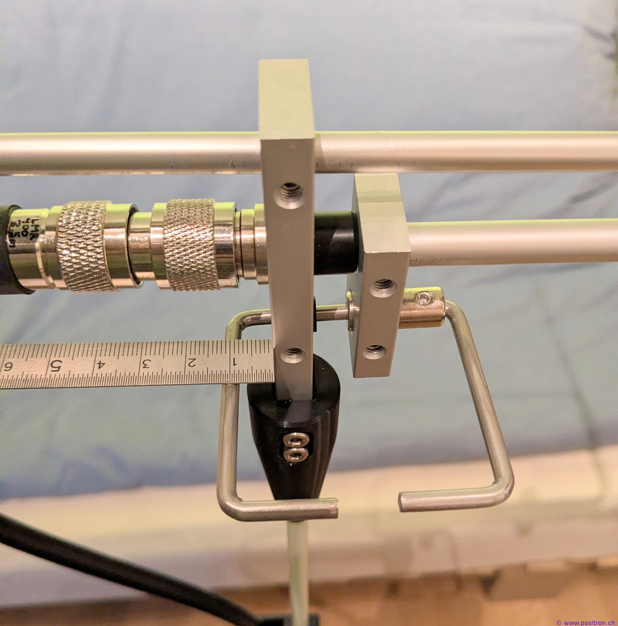
|
||||||||||||||||||||||
|
Black: C=8 mm Red: C=13 mm The influence is minor. Odd. |

|
||||||||||||||||||||||
|
|||||||||||||||||||||||
Influence of dimension D |
|||||||||||||||||||||||
| Dimension D = 8 mm. | 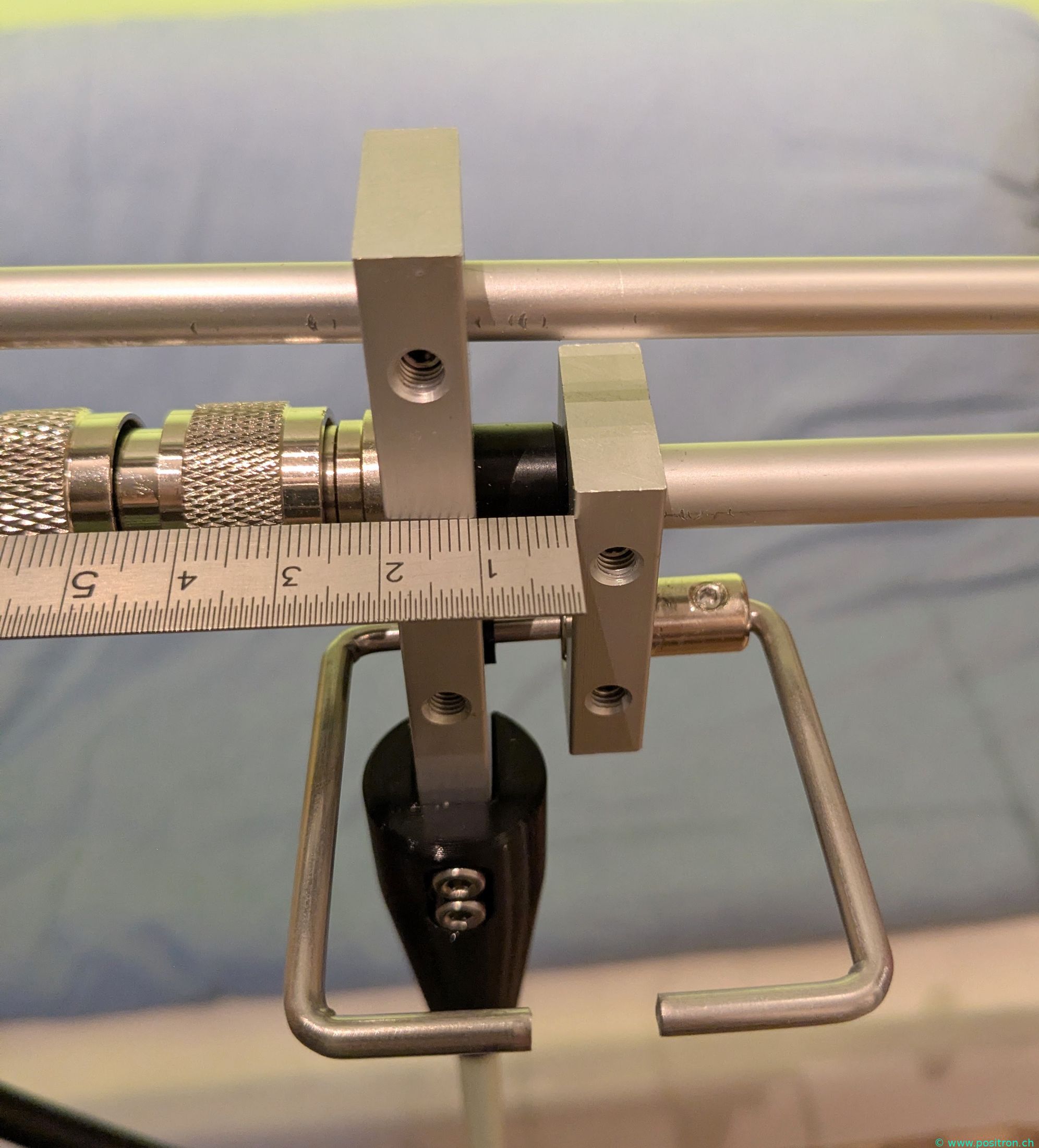
|
||||||||||||||||||||||
|
Black: D=8 mm Red: D=13 mm |
|
||||||||||||||||||||||
|
Black: D=8 mm Red: D=13 mm Here I would have expected the coupling to increase and the circle in the Smith chart to grow larger. The effect is not entirely clear to me. |
|
||||||||||||||||||||||
Influence of dimension E |
|||||||||||||||||||||||
| Dimension E = 32 mm. | 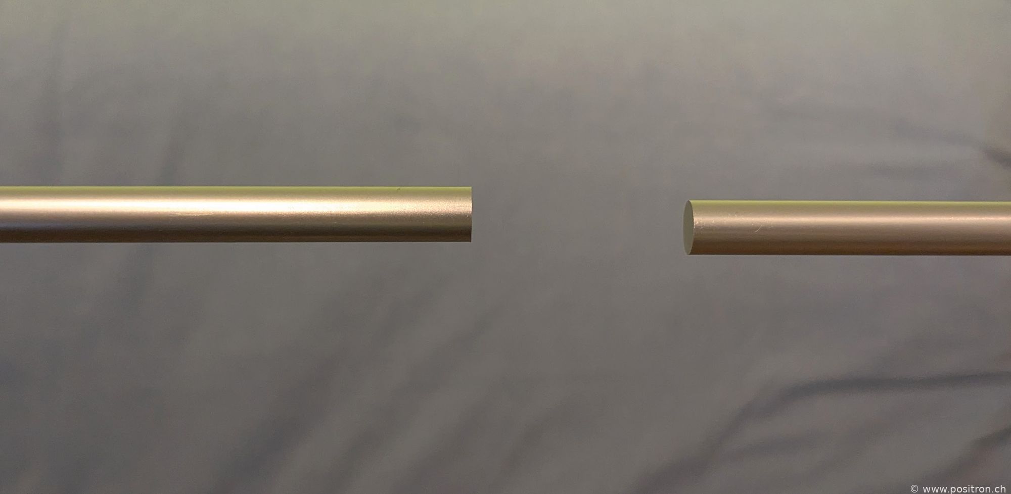
|
||||||||||||||||||||||
| A spacer printed from PETG is used to spread the loop apart. | 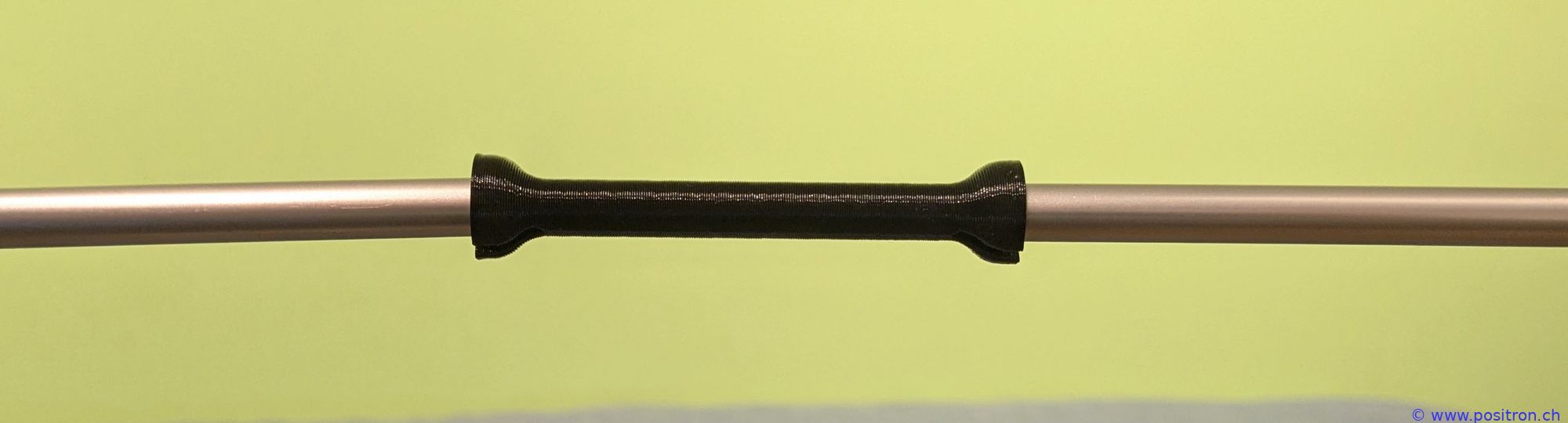
|
||||||||||||||||||||||
|
Black: E=32 mm Red: E=70 mm Larger gap, less capacitance, higher resonance frequency. |

|
||||||||||||||||||||||
|
Black: E=32 mm Red: E=70 mm Little influence. |
|
||||||||||||||||||||||
Findings |
|||||||||||||||||||||||
|
Changing one dimension always affects several properties, resonance frequency and coupling, and this with the two frequency ranges. Yes, it is not easy to write instructions on how to tune this antenna. Even though there is no simple recipe, after a bit of trial and error I found a satisfying setting. If anyone has a better understanding of how this antenna works, I would be grateful for any hints. |
|||||||||||||||||||||||
Outdoor Use |
|||||||||||||||||||||||
|
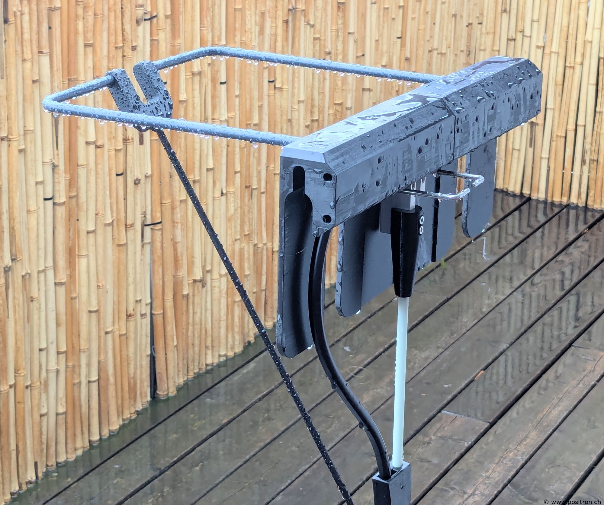
On a tripod on the balcony in the rain. Painted grey so the antenna is less conspicuous.
Supported on the left with a fiberglass rod. We regularly have birds visiting, and without this support a heavy crow landing on the antenna would create an enormous torque on the small grub screw pressing against the 8 mm diameter aluminum loop. Cover mounted on the right. The cover is simply slid over from top to bottom. |
 |
||||||||||||||||||||||
| Under the cover it stays quite dry. In particular, the connectors are protected. | 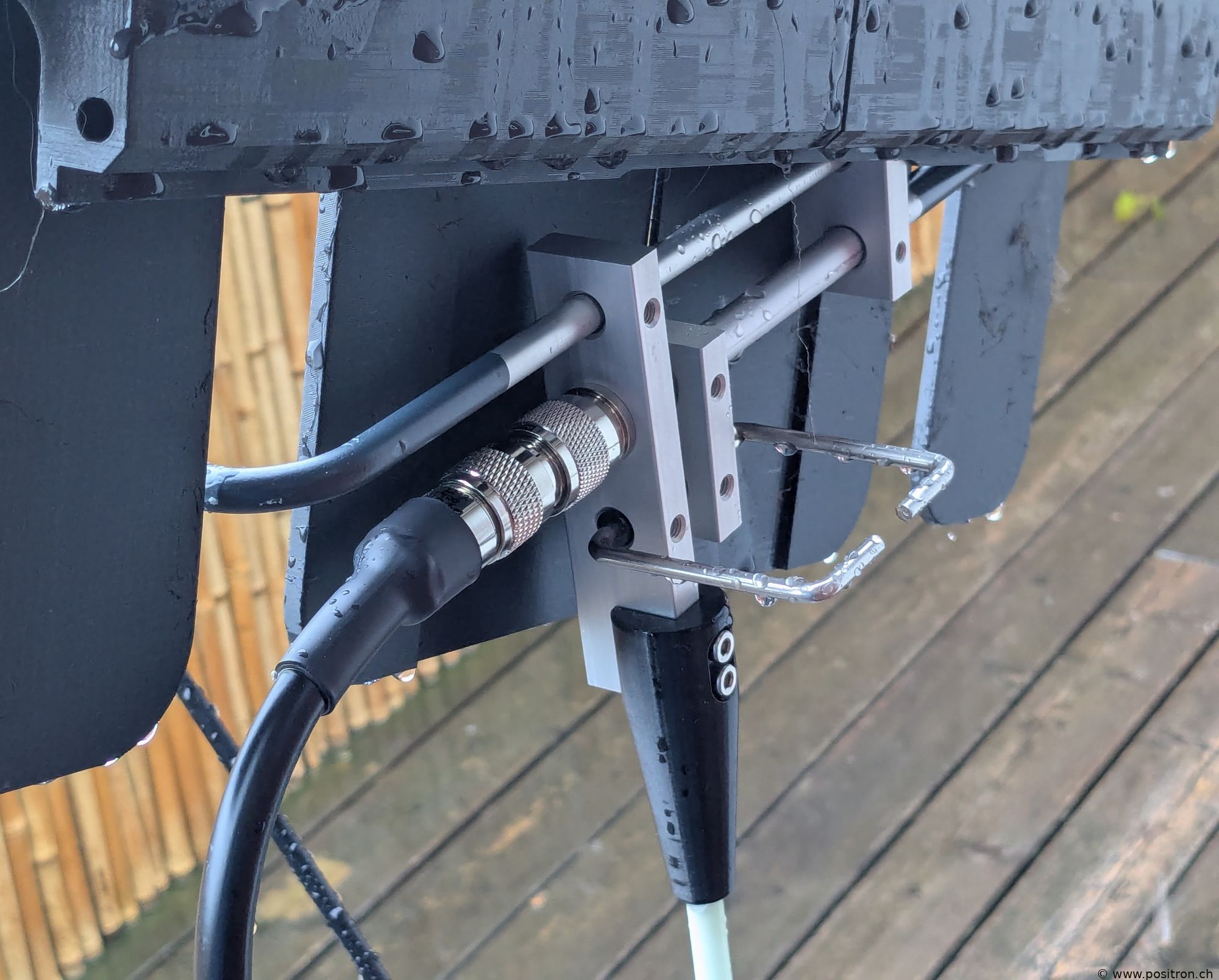 |
||||||||||||||||||||||