You are viewing the printable version of the page: Various -> FT-991A output power
I bought an FT-991A transceiver and measured the output power.
Bought in Switzerland in November 2025, SN 4F910844, Europa Version
I updated the firmware of the FT-991A:
| Component | Error |
|---|---|
| Attenuator 30 dB | ± 0.3 dB |
| Attenuator 20 dB | ± 0.4 dB |
| Power meter A with AD8307 up to 30 MHz | ± 0.5 dB |
| Power meter B above 50 MHz | ± 1 dB, not checked |
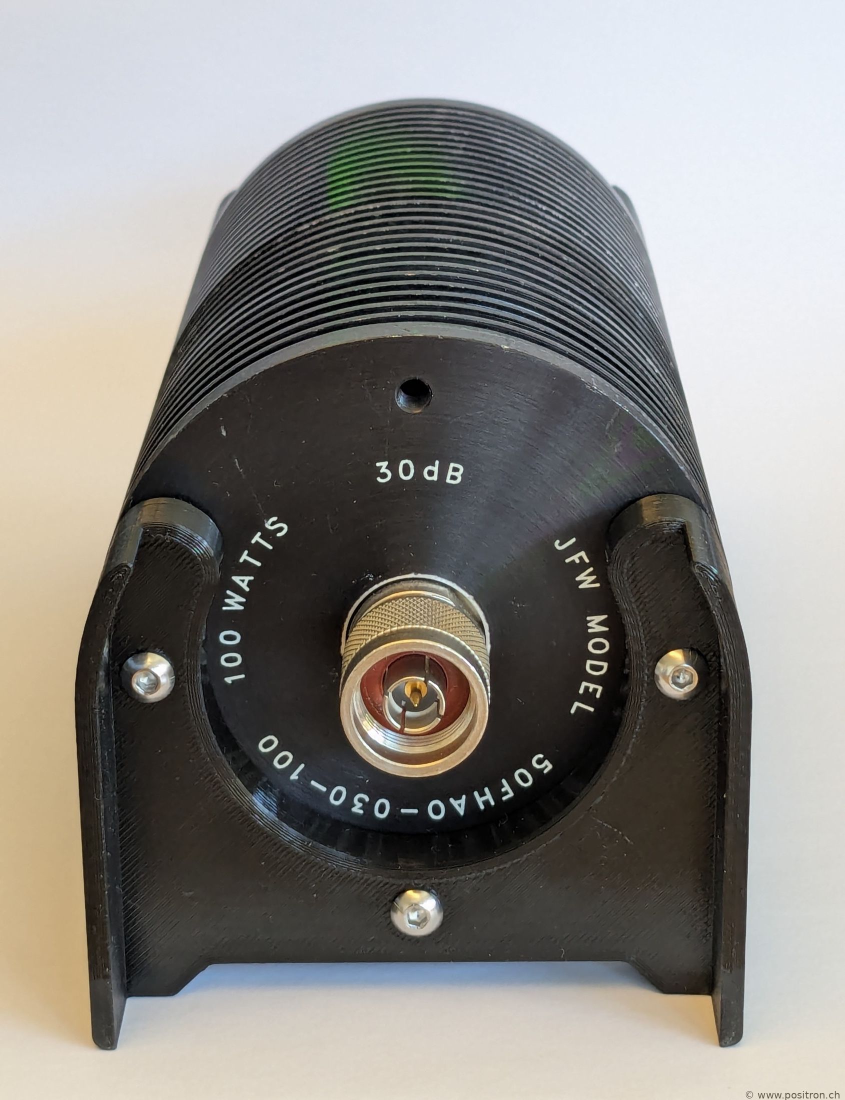
| attenuator 30 dB, 100 watt | |
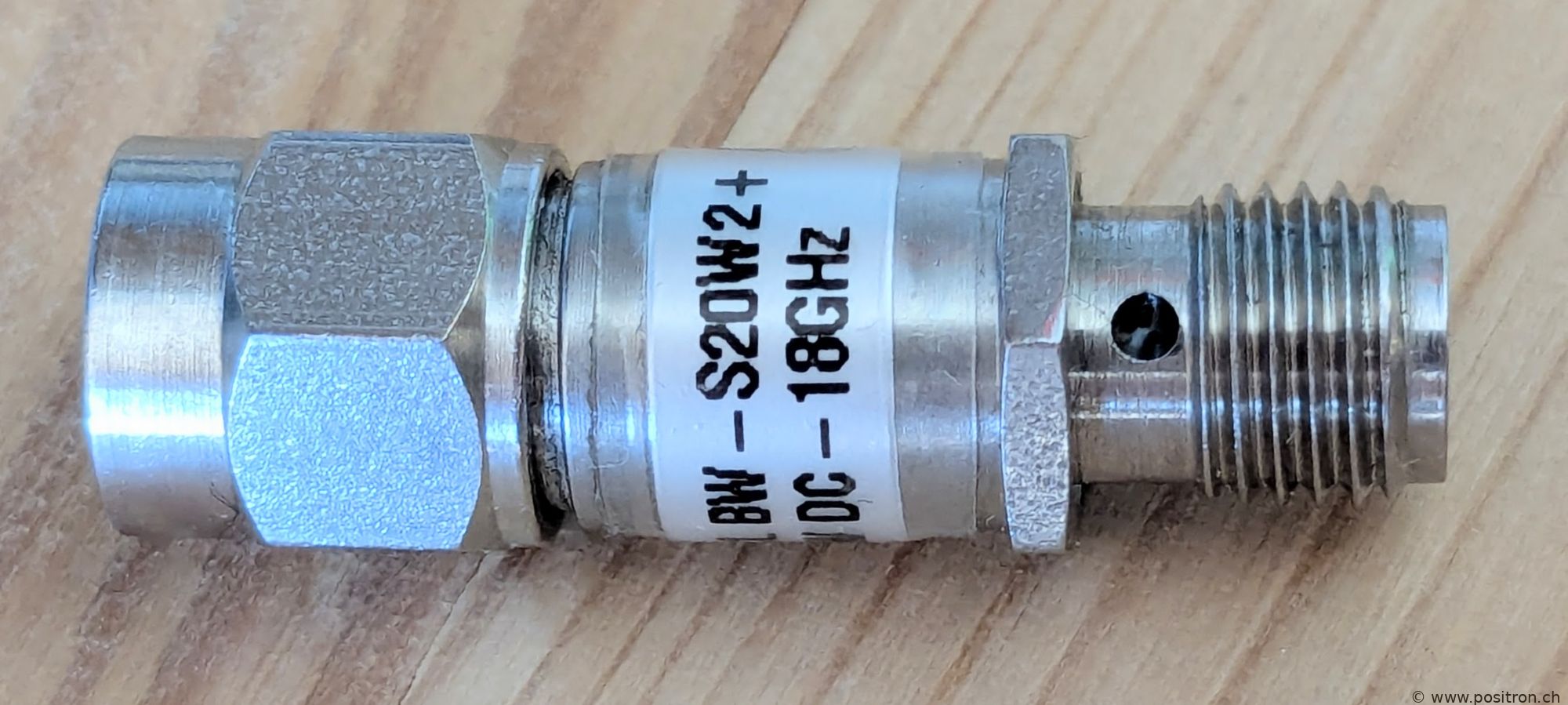
| attenuator 20 dB | |
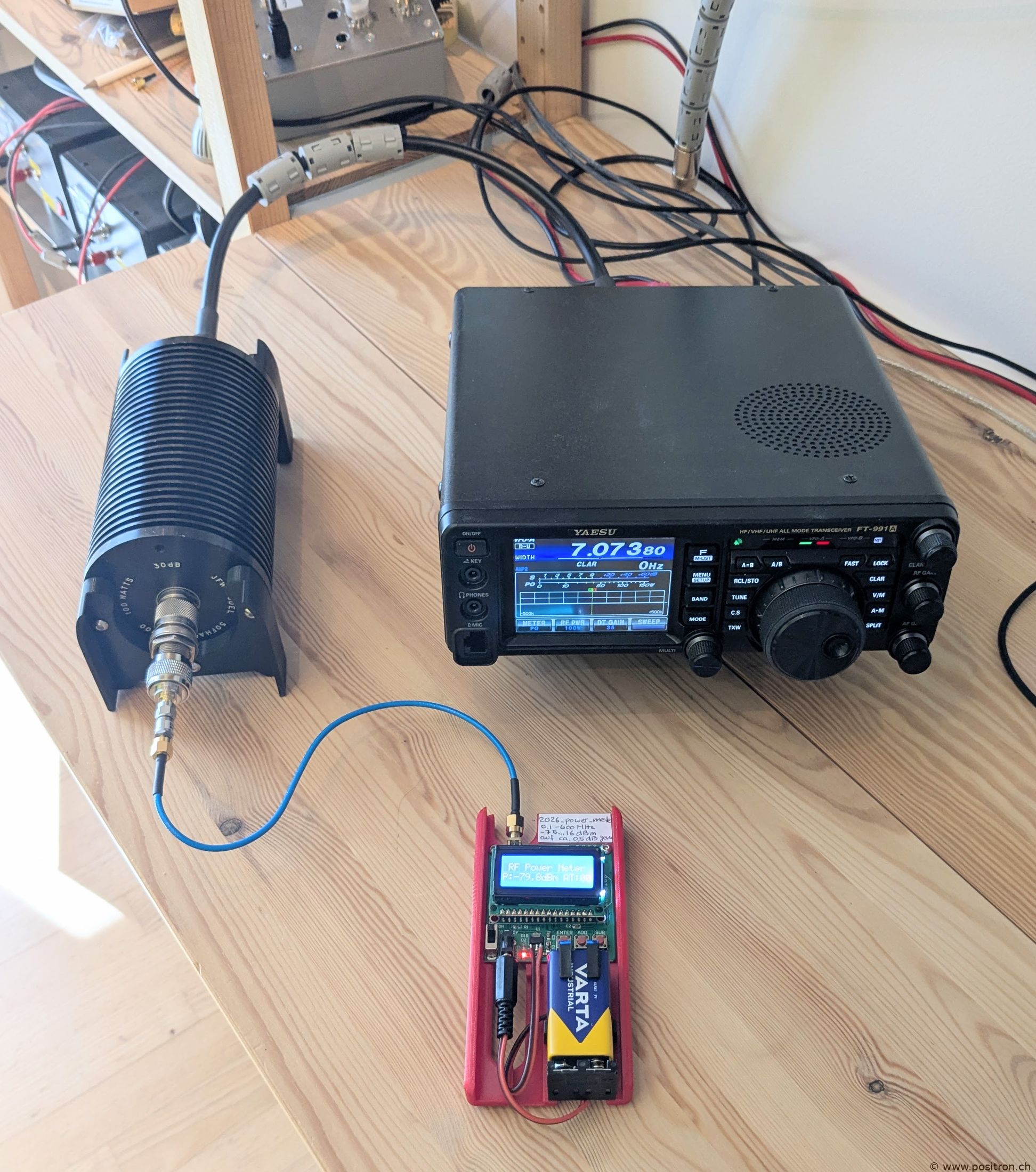
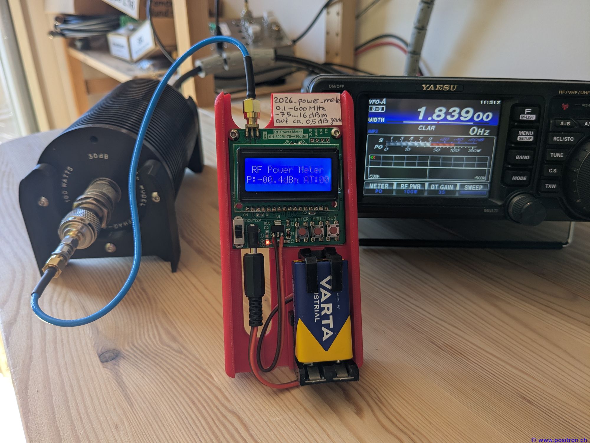
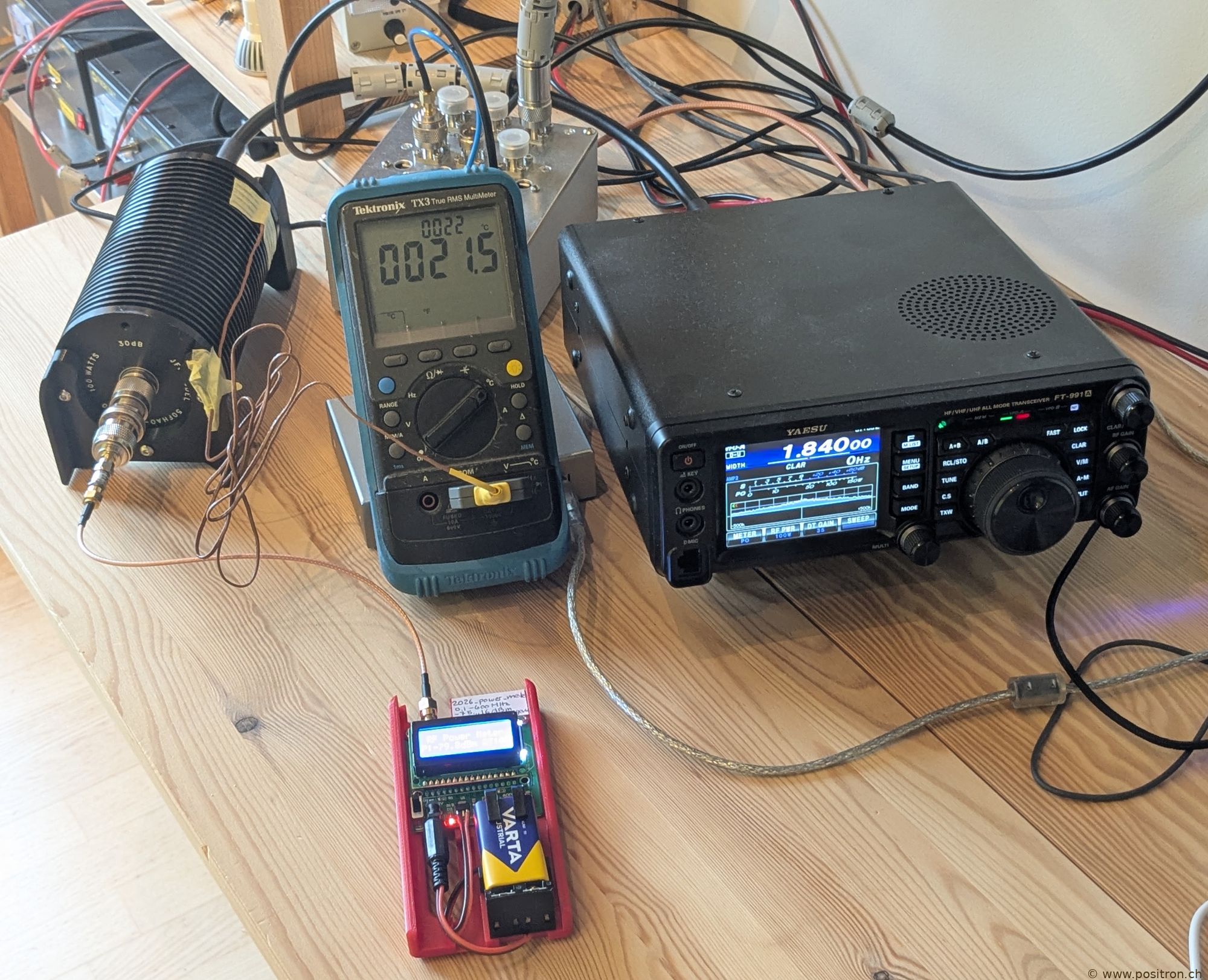
| FT-991A with connected attenuators and power meter A. | |
|
|
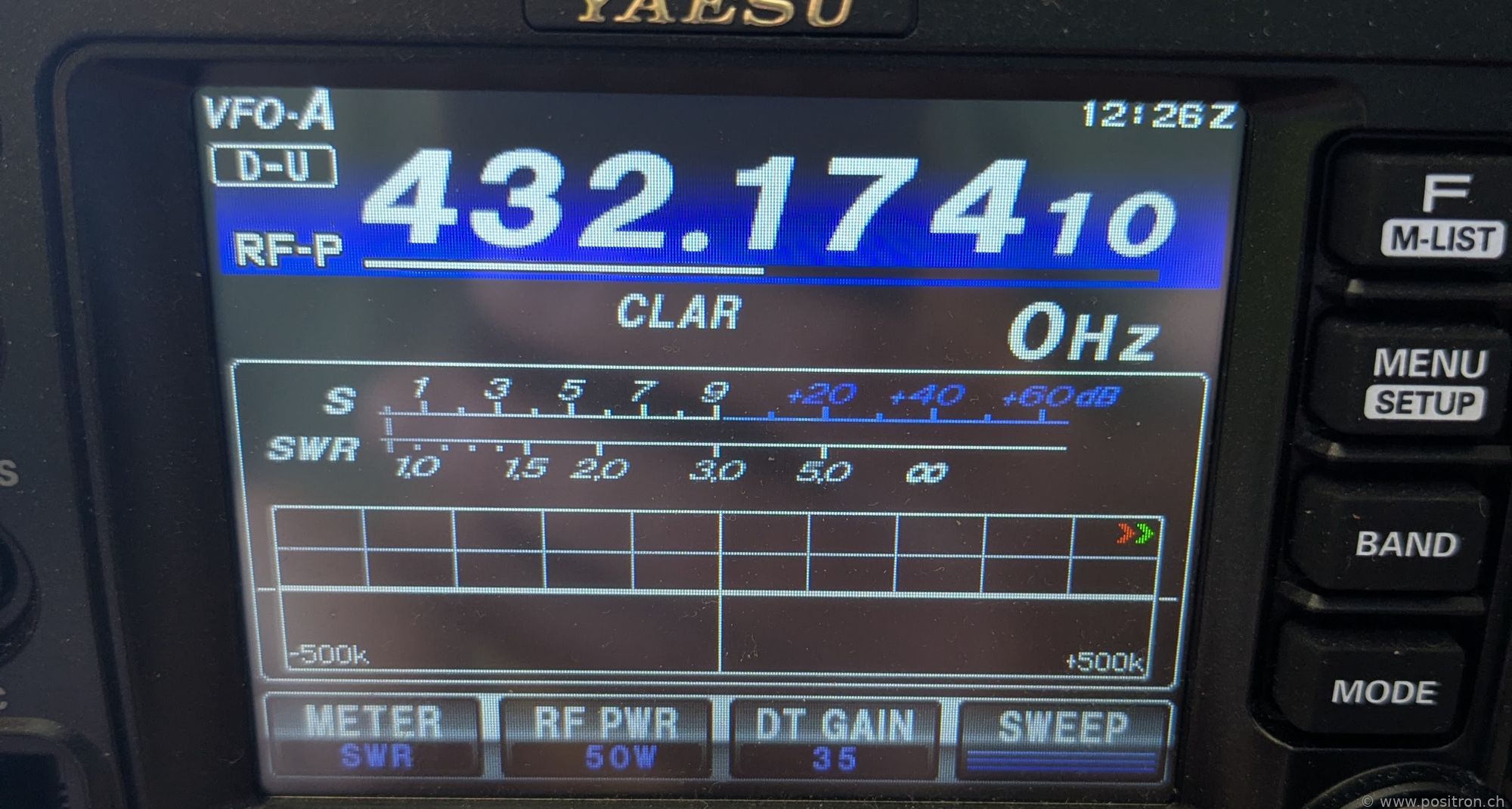
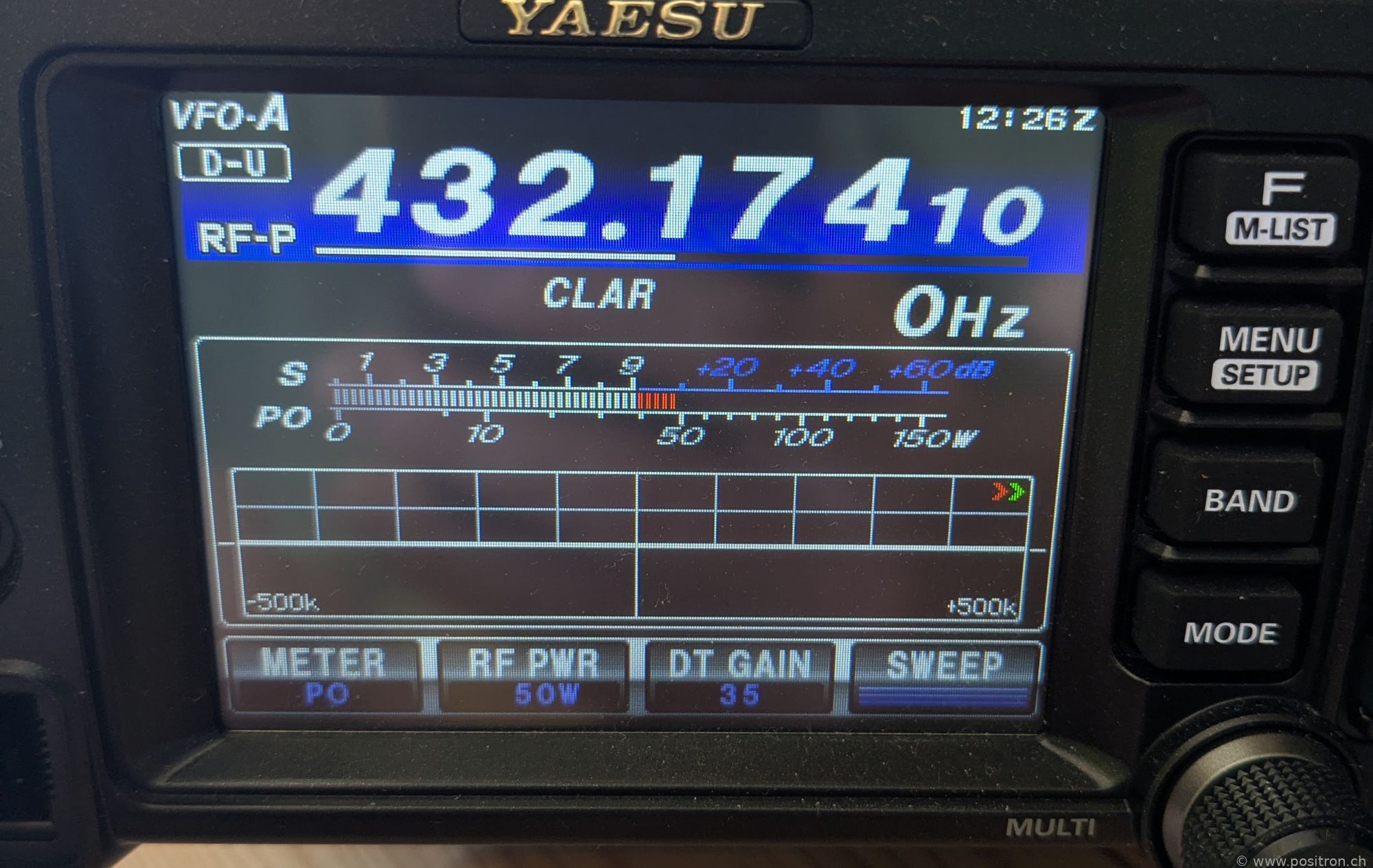
| Example test at 432 MHz with 50 W target power. SWR clean at 1.0 | |
|
|
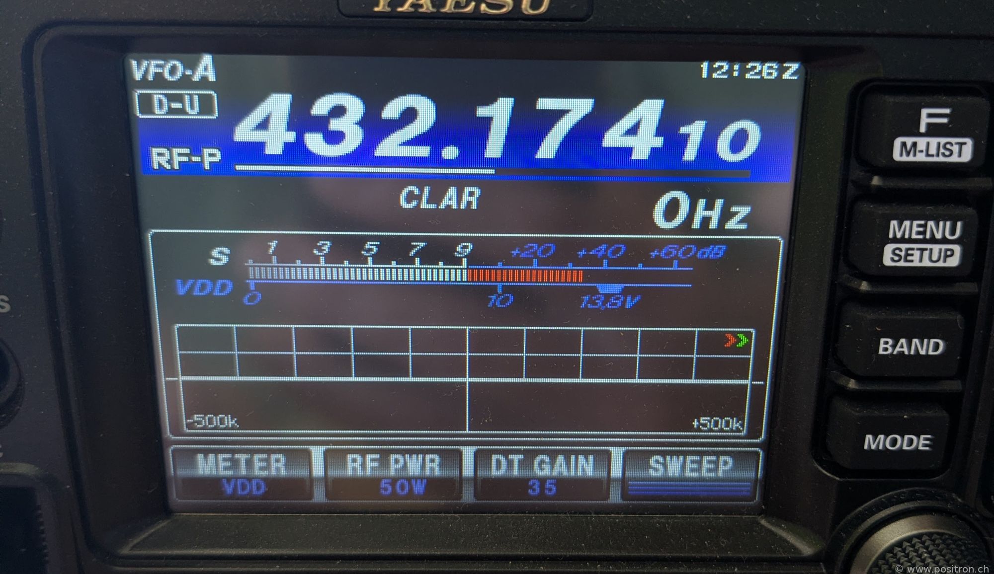
| VDD 12.3 V? Dear Yaesu developers, this scale is anything but easy to read. One tick mark per volt on the lower scale would not be a big luxury. Where I see 13.8 V labeled, it looks more like 13 V if I use the tick marks of the upper S-meter scale. A direct measurement with a multimeter at the power connector of the transceiver reads 12.93 V. | |
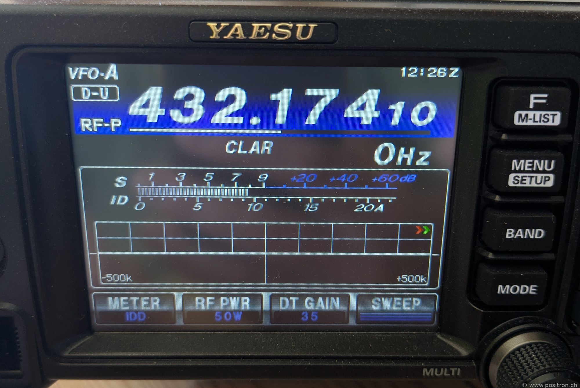
| IDD at 9.5 A is very low. According to the datasheet, I would expect about 15 A here. | |
| From the manual (FT-991A_OM_ENG_EH067M205_2111A-KS-1_manual) I read: 13.8 V ± 15% : 11.73 V to 15.87 V. The 12.3 V I read would therefore still be well within the allowed range. | |
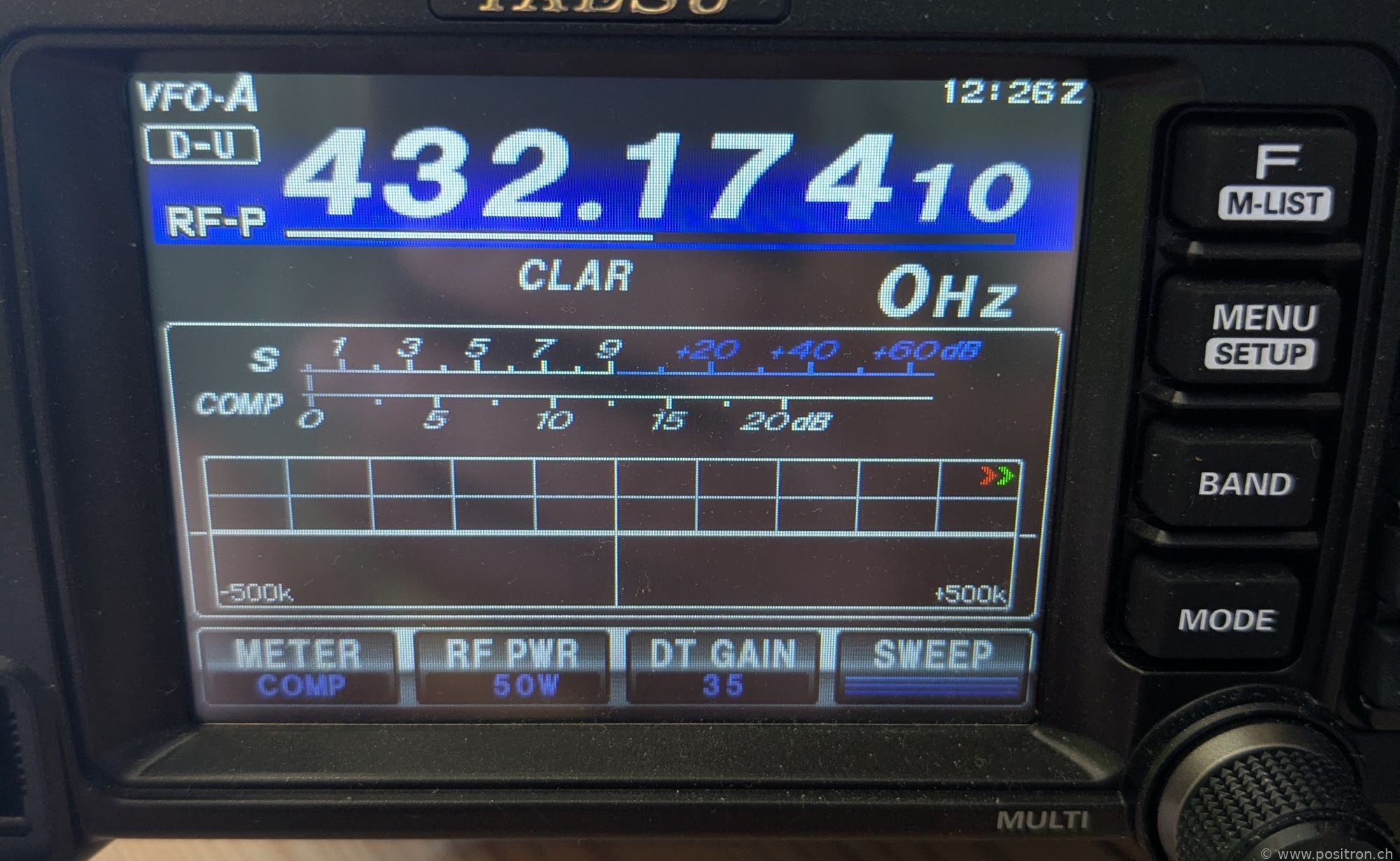
| The display shows a transmit power of 50 W. If my audio drive were too low, or the supply voltage too low, the displayed transmit power would also be lower. | |
For the measurement I use WSJT-X in tune mode and observe that the AGC slightly deflects. I adjust "RF PWR" on the transmitter. For a few measurements, I switched to FM and transmitted using the hand microphone as a cross-check. The power was the same.
I measured the voltage directly at the connector of the FT-991A: at 432 MHz, 13.46 V idle and 12.93 V while transmitting. At the lower frequencies: 13.46 V idle and 12.76 V while transmitting.
The power can be selected from 5 W to 100 W in 1 W steps on the HF bands, and from 5 W to 50 W in 1 W steps on the higher bands.
I measured at several frequencies and at 5 different power levels.
| Frequency (MHz) | Set (W) | Measured (W) | Ratio | Power Meter |
|---|---|---|---|---|
| 1.8 | 100 | 91.2 | 91% | A |
| 1.8 | 50 | 45.7 | 91% | A |
| 1.8 | 25 | 20.9 | 84% | A |
| 1.8 | 10 | 9.1 | 91% | A |
| 1.8 | 5 | 4.6 | 91% | A |
| 3.6 | 100 | 95.5 | 95% | A |
| 3.6 | 50 | 46.8 | 94% | A |
| 3.6 | 25 | 22.4 | 90% | A |
| 3.6 | 10 | 9.3 | 93% | A |
| 3.6 | 5 | 4.8 | 96% | A |
| 7.1 | 100 | 87.1 | 87% | A |
| 7.1 | 50 | 42.7 | 85% | A |
| 7.1 | 25 | 20.4 | 82% | A |
| 7.1 | 10 | 8.5 | 85% | A |
| 7.1 | 5 | 4.5 | 89% | A |
| 10 | 100 | 87.1 | 87% | A |
| 10 | 50 | 45.7 | 91% | A |
| 10 | 25 | 20.9 | 84% | A |
| 10 | 10 | 8.9 | 89% | A |
| 10 | 5 | 4.8 | 96% | A |
| 14 | 100 | 81.3 | 81% | A |
| 14 | 50 | 43.7 | 87% | A |
| 14 | 25 | 20.9 | 84% | A |
| 14 | 10 | 8.5 | 85% | A |
| 14 | 5 | 4.8 | 96% | A |
| 28 | 100 | 81.3 | 81% | A |
| 28 | 50 | 42.7 | 85% | A |
| 28 | 25 | 20.0 | 80% | A |
| 28 | 10 | 8.5 | 85% | A |
| 28 | 5 | 4.8 | 96% | A |
| 50 | 100 | 89.1 | 89% | B |
| 144 | 50 | 60.3 | 121% | B |
| 432 | 50 | 61.7 | 123% | B |
| As an alternative measurement method without a power meter, I also measure the heating of the 30 dB attenuator after 90 s of transmission. | 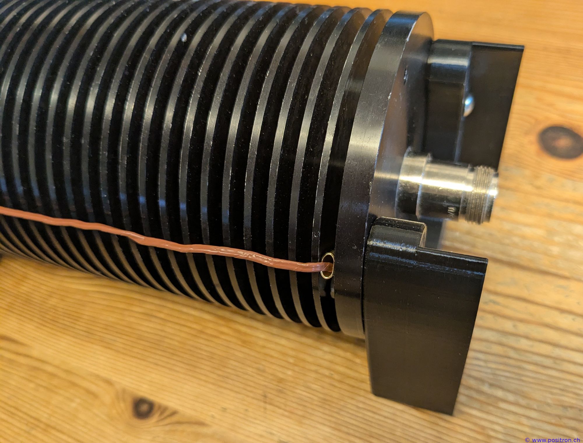 |
|
1.8 MHz 100W heating 18.6°C 432 MHz 50W heating 10°C Yes, the ratio of the heating matches quite nicely with the ratio of the expected power. |
 |
The transmit power appears to match the specifications very nicely.