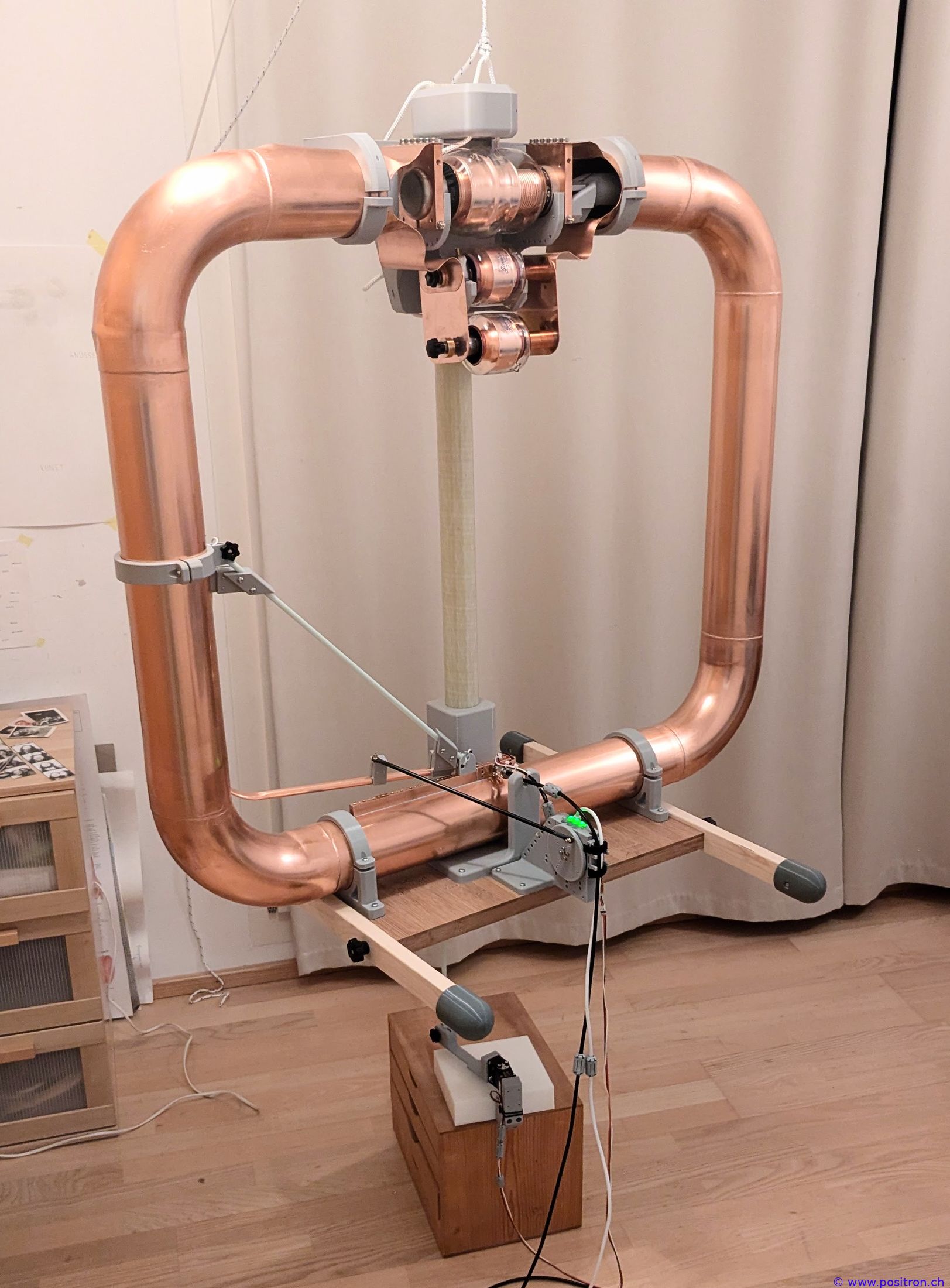
Selfmade small magnetic loop HF antenna:
- 1 m loop diameter
- 100 mm diameter copper tube
- 10 m to 40 m
- 60 m to 160 m by switching in fixed capacitors
- Frequency, impedance matching and azimuth are all adjusted automatically by servo motors.
- Name: Tubby
Further information can be found in a paper.
You can find an overview of different magnetic loop antennas with detailed technical data:
https://petermaerki.github.io/magloop_field/index.html?page=compare
(Static Page https://petermaerki.github.io/magloop_field/generated_compare.html)
And a calculator:
petermaerki.github.io/magloop_field/index.html?page=calculator
Various Photos of the Magnetic Loop Construction and Additional Information Supplementing the Paper
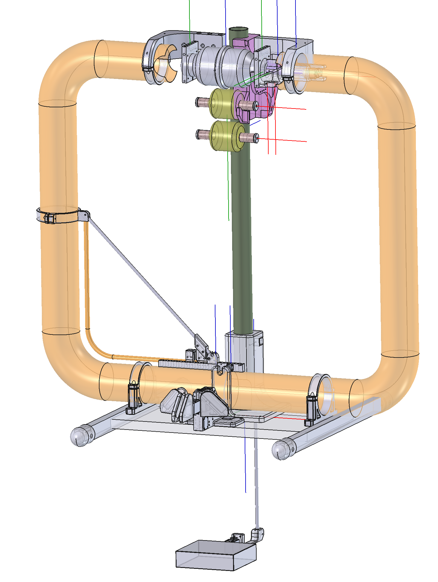
All parts were modelled in CAD.
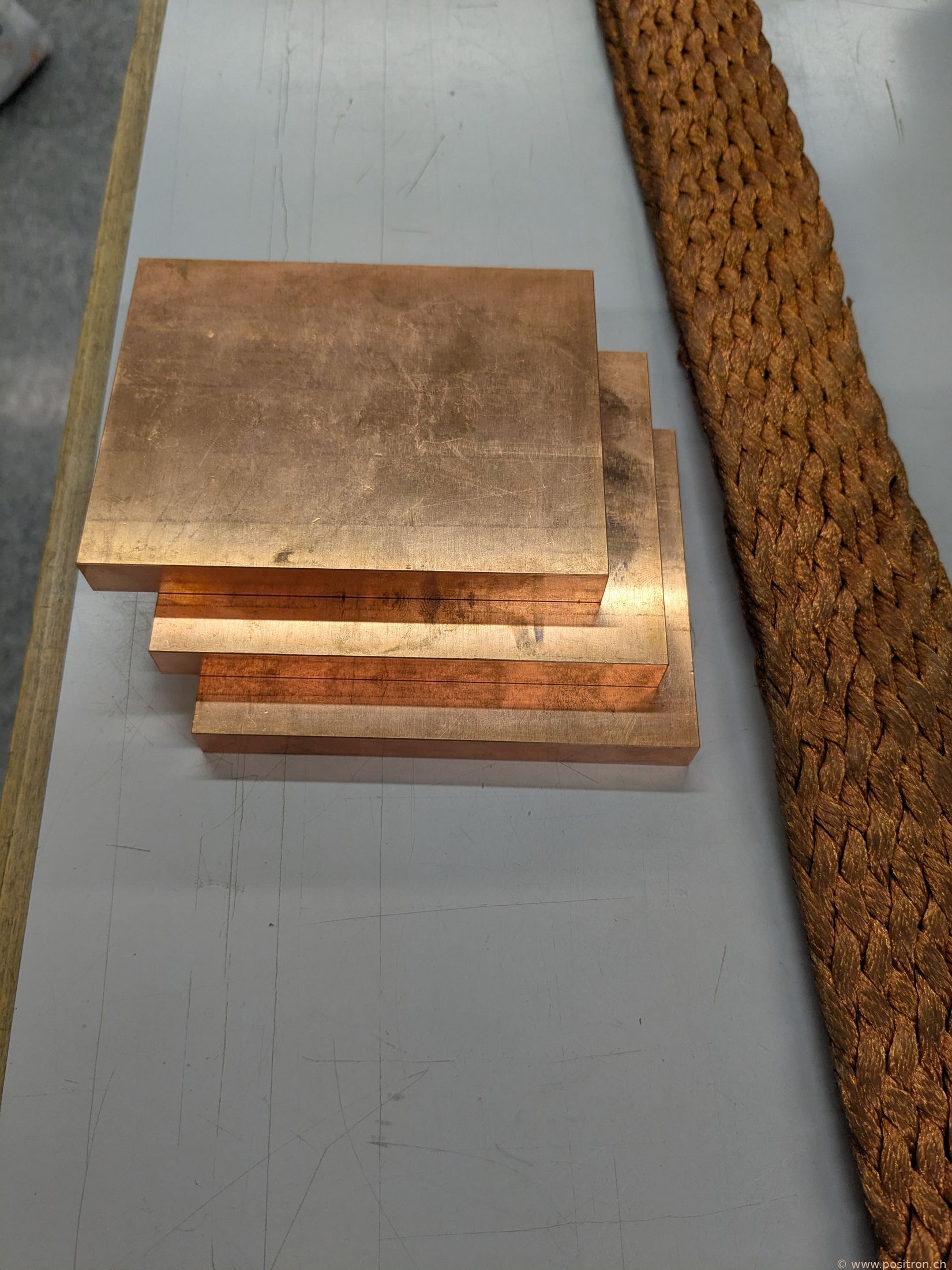
Raw material.
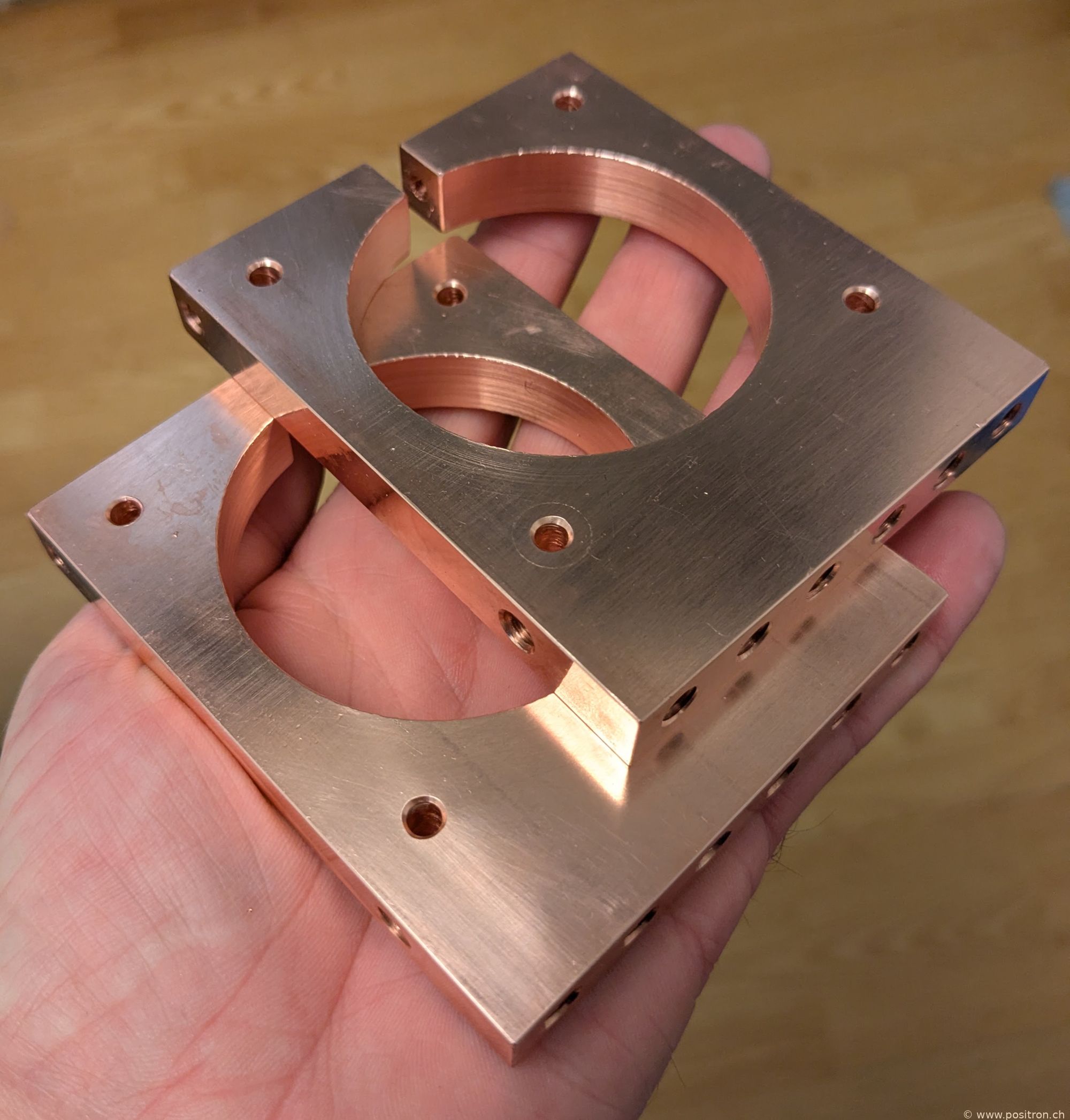
Capacitor End Caps
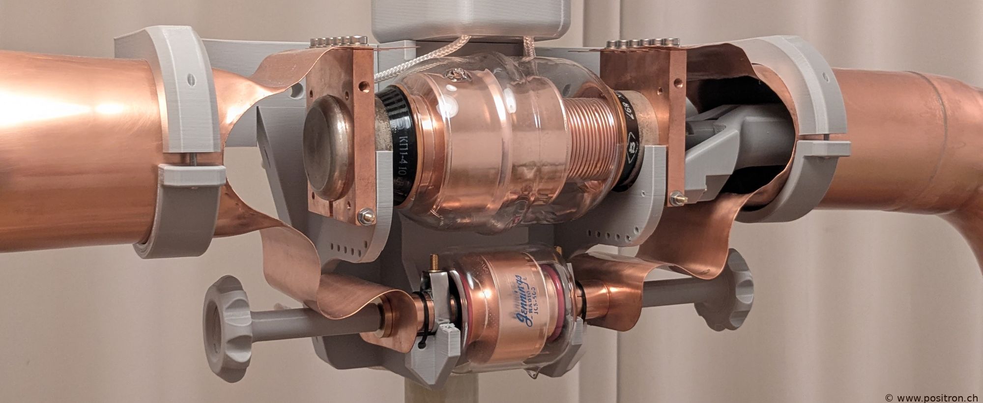
Clamps manufactured from 12 mm OF copper as a transition from the capacitor ends to the copper tubes.
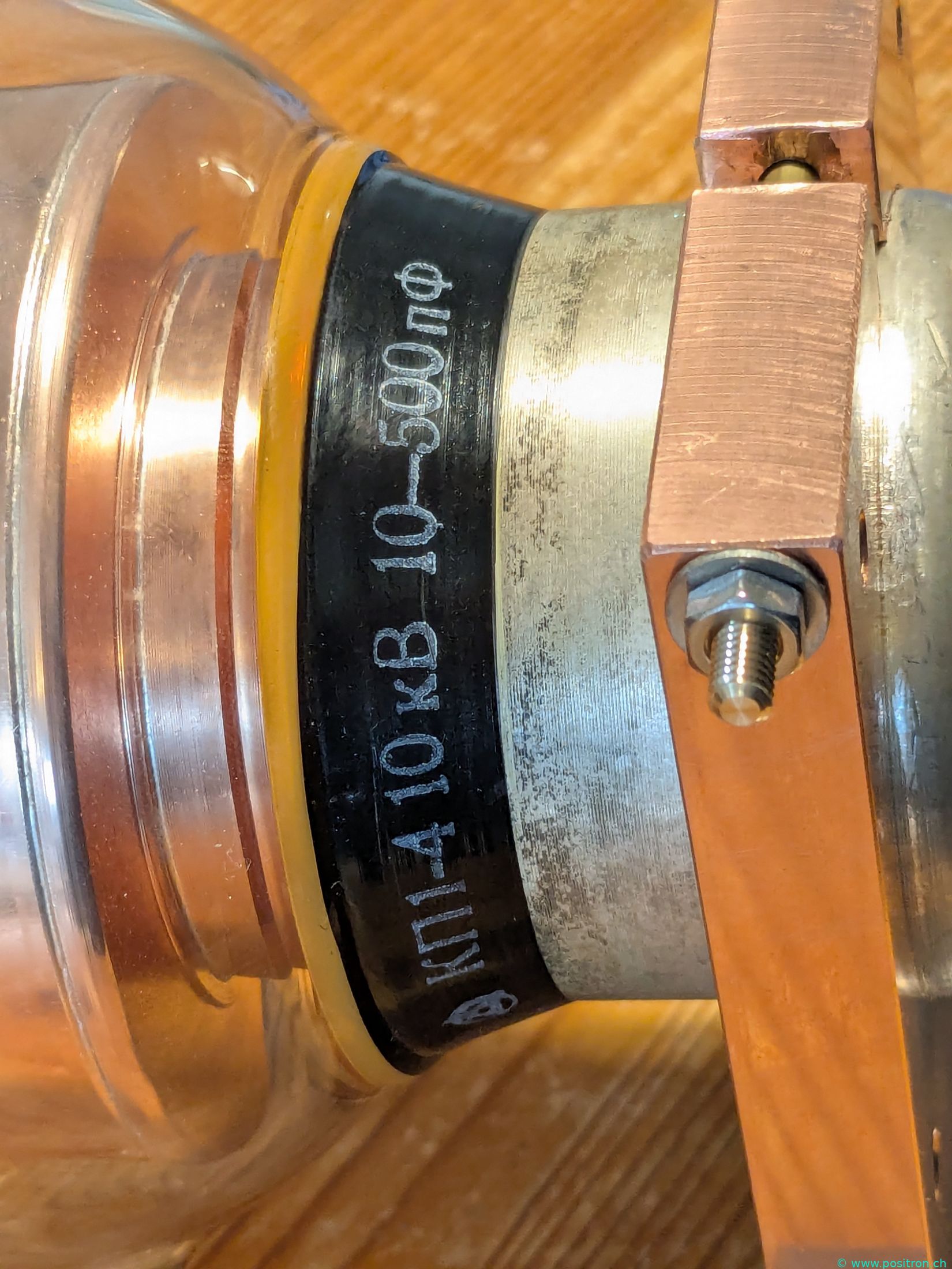
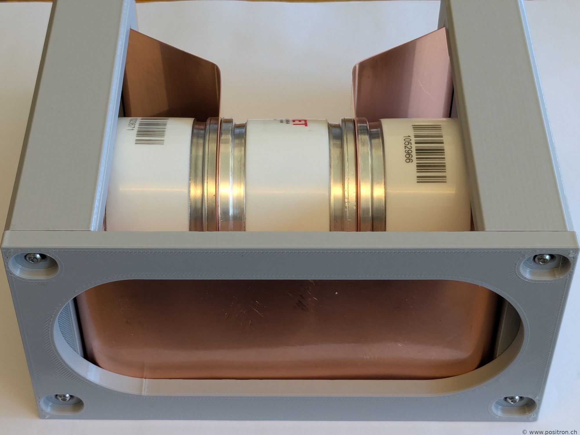
Detail: transition from the side plates to the capacitor KP1-4.
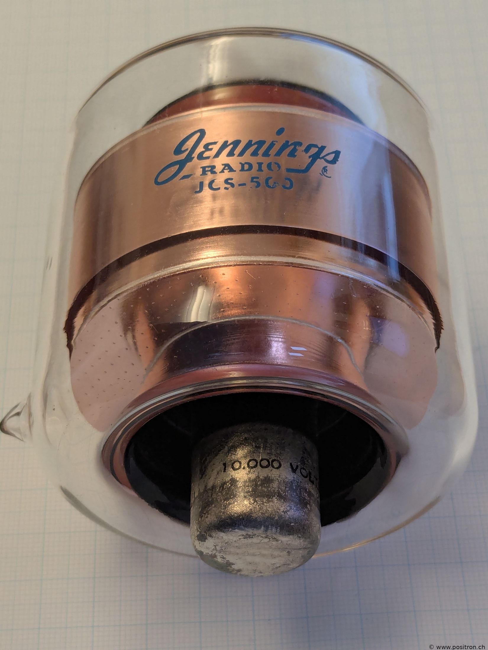
Jennings Capacitors
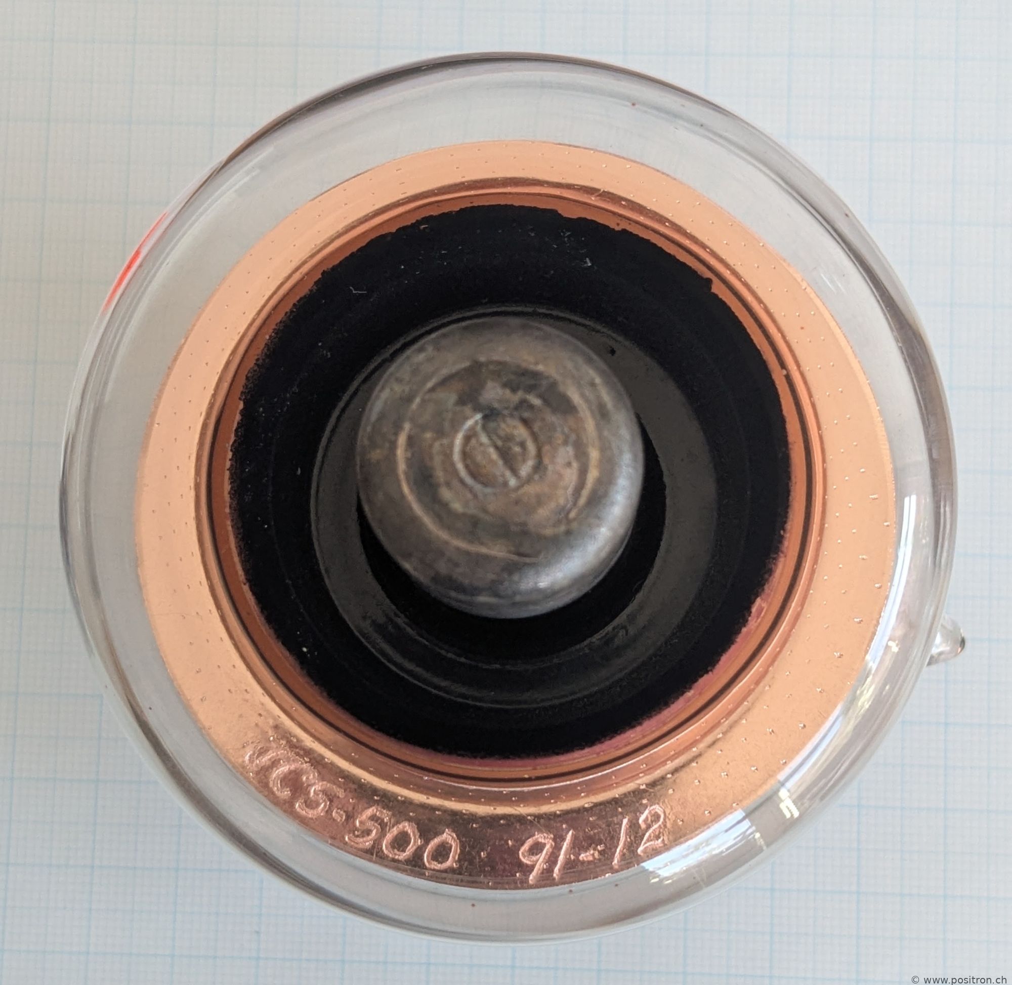
Jennings JCS-500-10S vacuum capacitor
The type and manufacturing date are engraved on the inside of the copper.
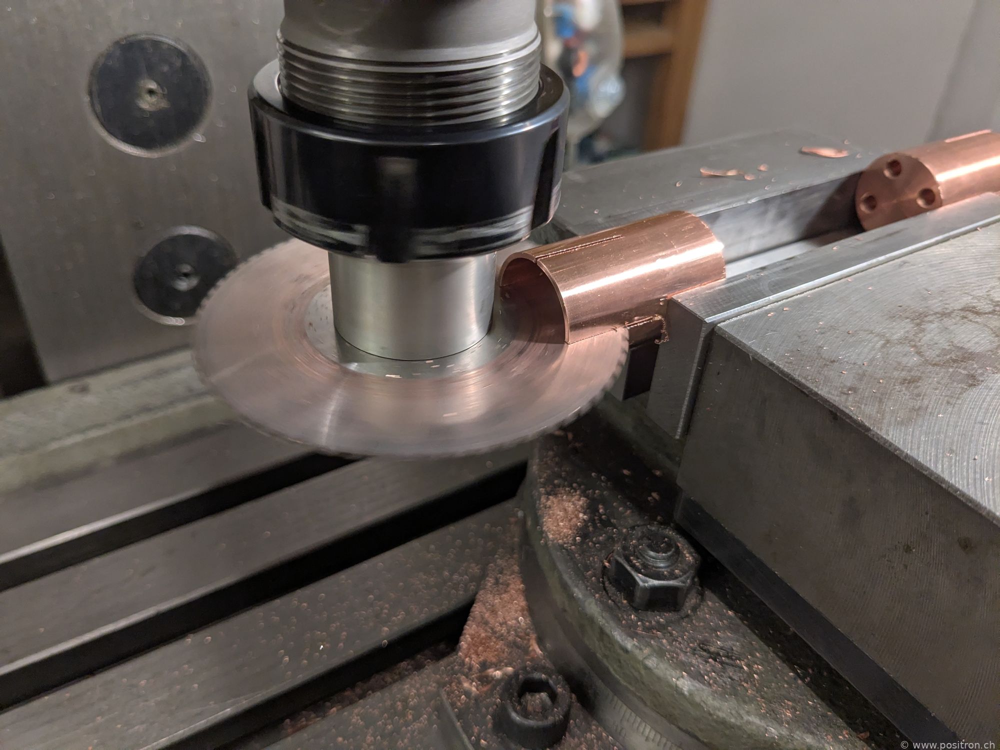
Milling end caps from OF copper.
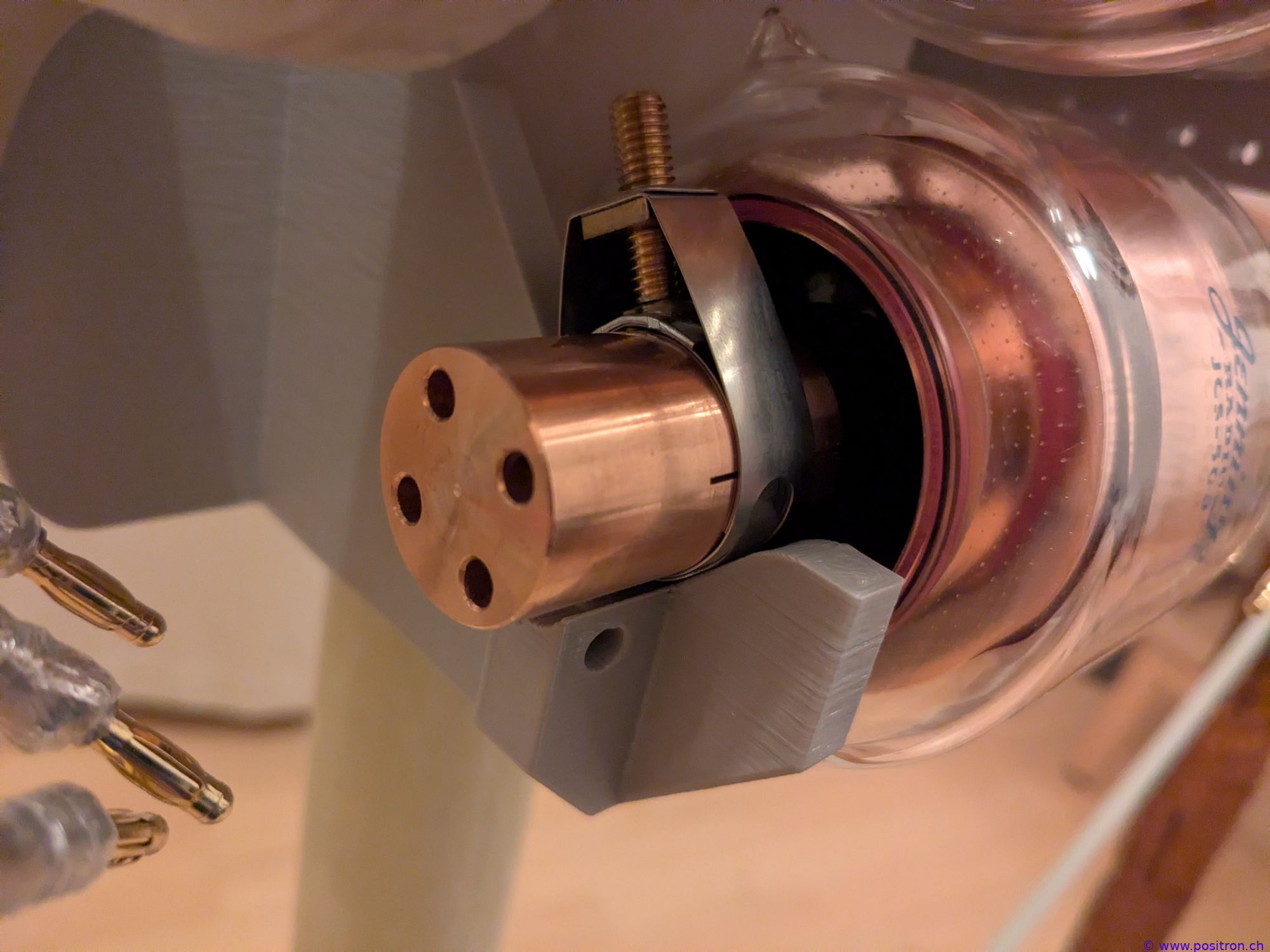
End cap clamped onto the capacitor with a hose clamp. Acid-free vaseline is applied between the capacitor and end cap to prevent the surfaces from oxidising.
In this first version, I wanted to connect the loop using cables and 4 mm banana plugs. Hence the 4 matching 4 mm drill holes.
Experiment with Copper Braid
A first version of the loop using braided copper strap.
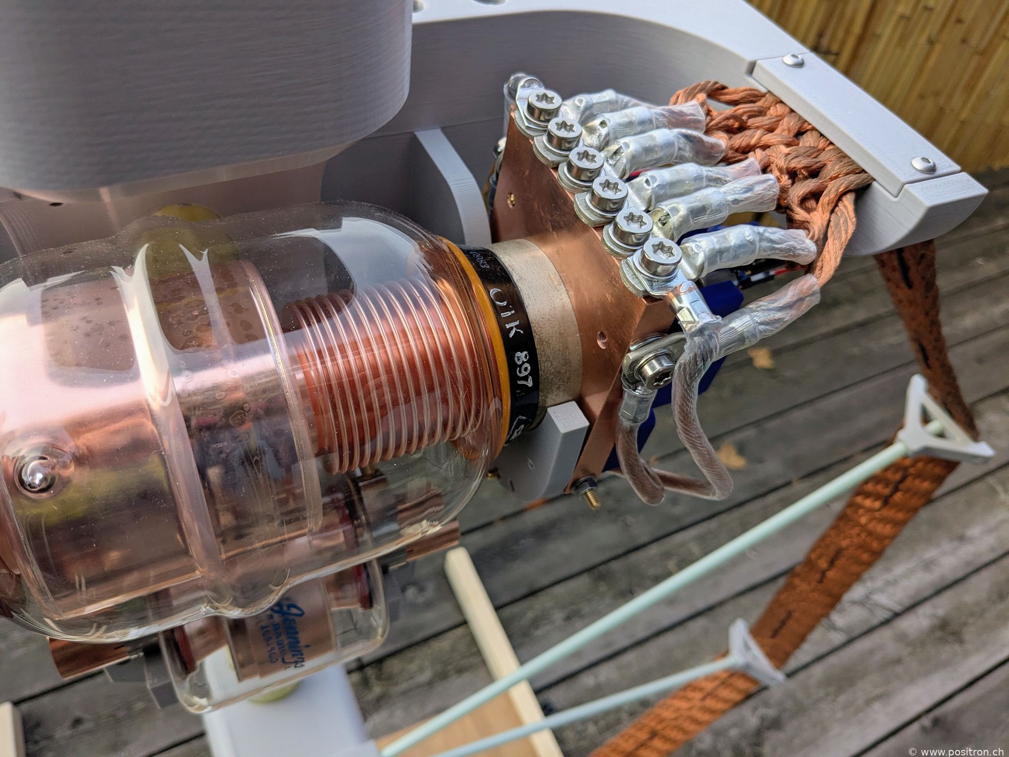
Cable lugs crimped and soldered.
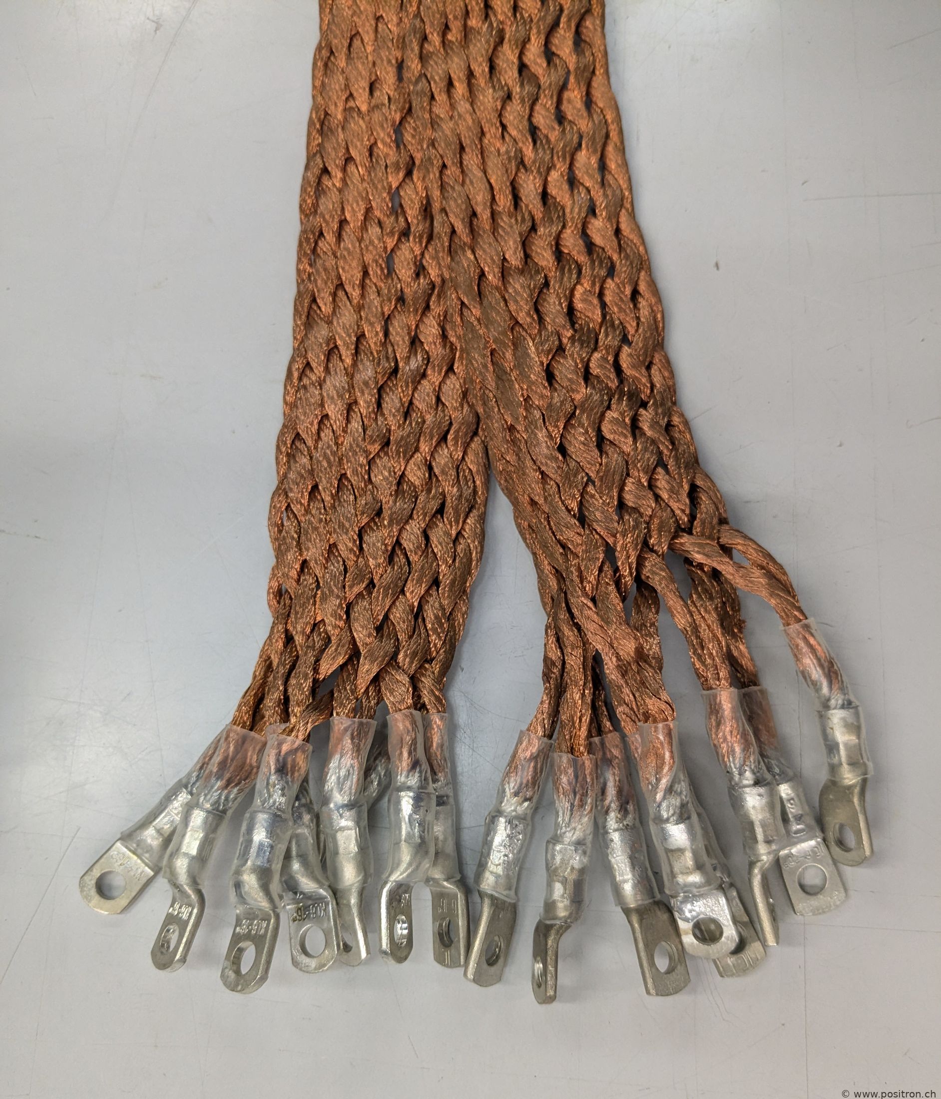
Braided copper strap: 1 kg per metre, width 50 mm, thickness 5 mm, 15 braided conductors. Total length 3 m.
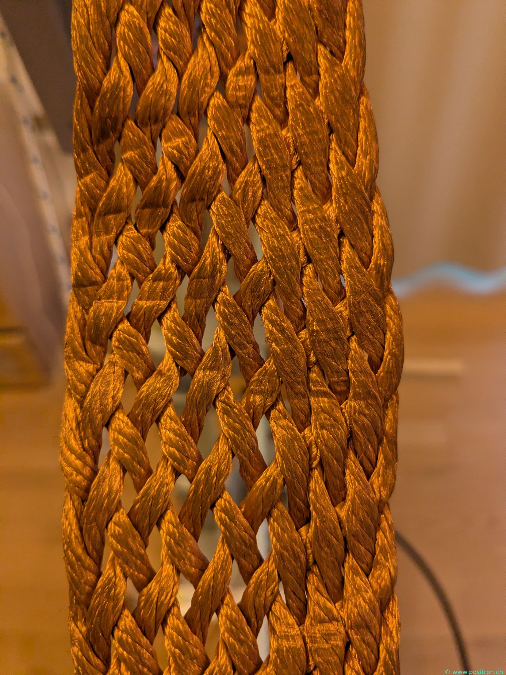
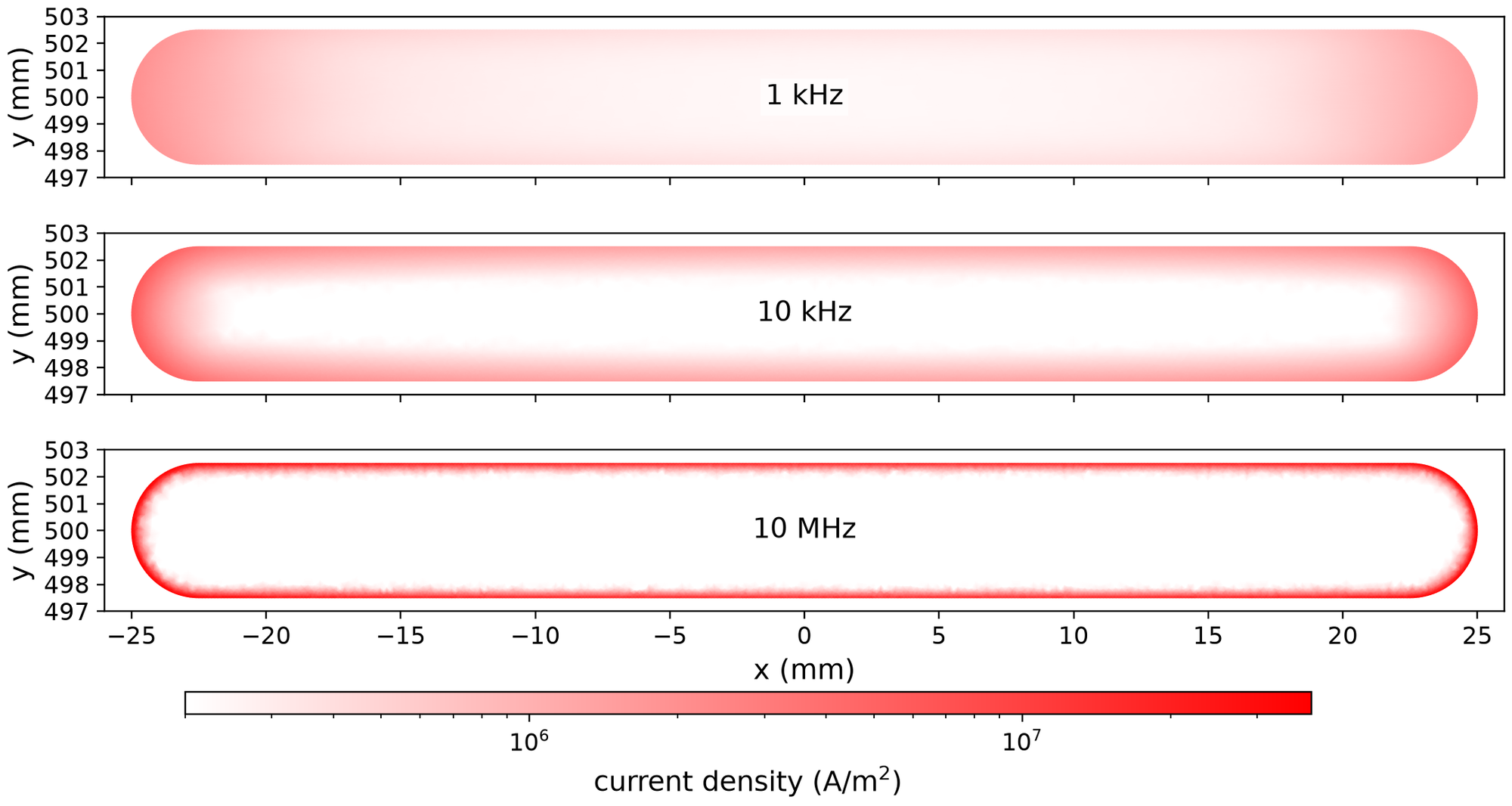
It turned out that the copper strap had very high losses. The conductors are very fine and the surface is slightly oxidised. Due to the skin and proximity effect, the current always wants to flow on the surface, preferably along the left and right edges. In a braid this is not possible. The current keeps switching between conductors and therefore passes through the oxide layer, causing resistive losses. The entire strap has more losses at 30 MHz than a single copper wire with a 1 mm diameter (rough estimate). The braid was an absolute disaster.
Braided "RF litz wire", with conductors cleanly isolated from each other (e.g. wrapped in silk), can have advantages around 1 MHz for example. For an HF antenna operating up to 30 MHz, as built here, RF litz wire is also not suitable.
Simulated current density in a copper strap with a cross-section comparable to the copper braid. At 10 MHz the current would flow almost exclusively on the surface.
A woven strap for a good earth connection is a different matter. The main goal there is to keep the inductance of the earth connection low. The resistive loss resistance due to the high frequency is probably not a major concern. A braided strap is therefore well suited for a low-impedance earth connection, but not for a magnetic loop antenna.
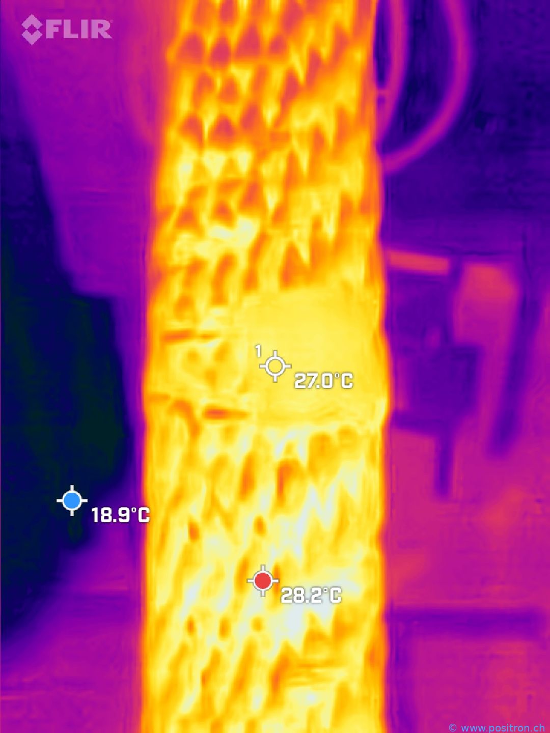
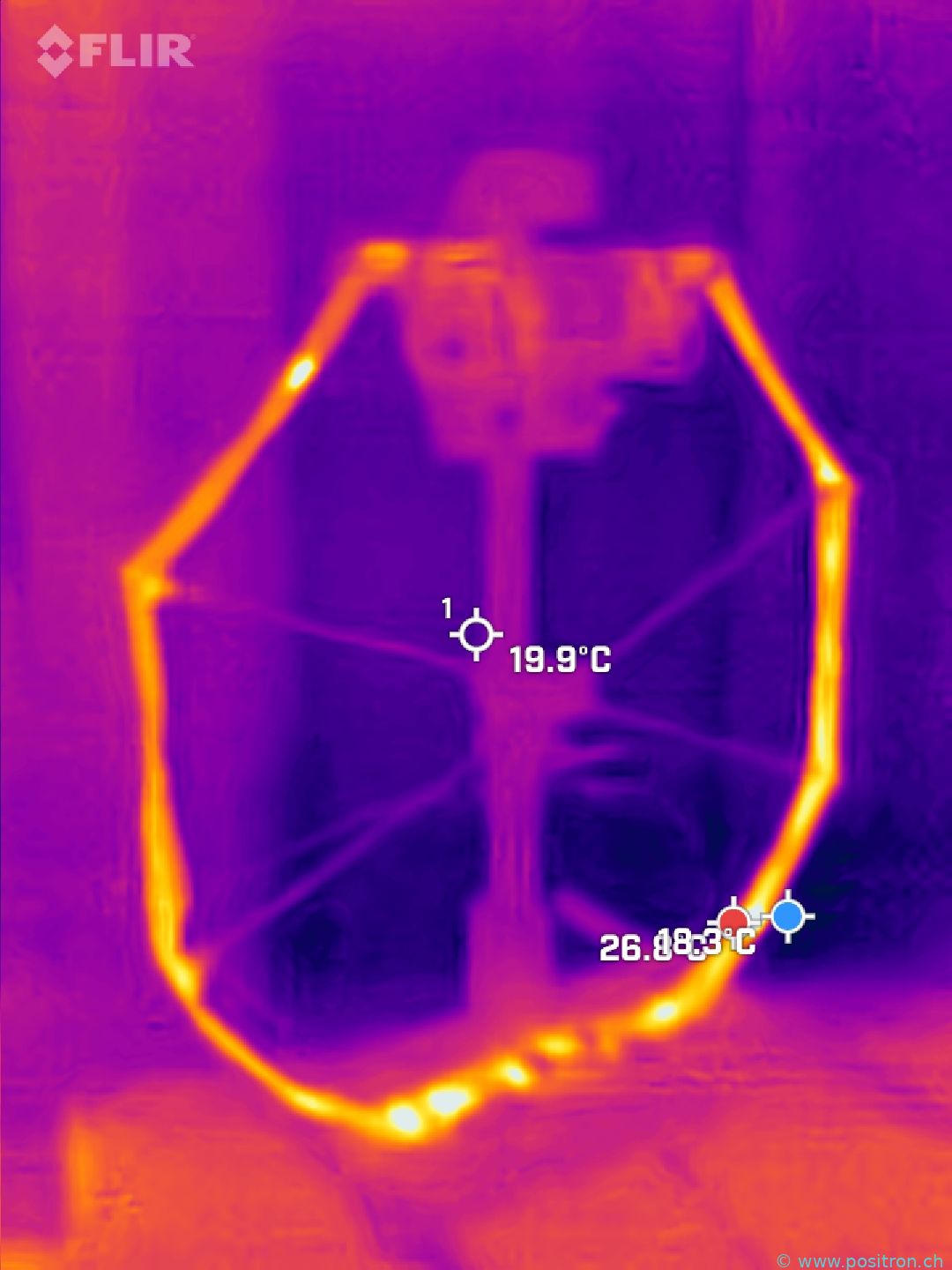
Thermal image of the copper strap after 10 minutes of transmitting at 100 watts. The strap is approximately 10 °C warmer than its surroundings.
Antenna after 10 minutes of transmitting at 100 W.
Copper Tube
After the failure with the braided strap I switched to copper tube – and if so, then with a really large diameter. A downpipe seemed appropriate.
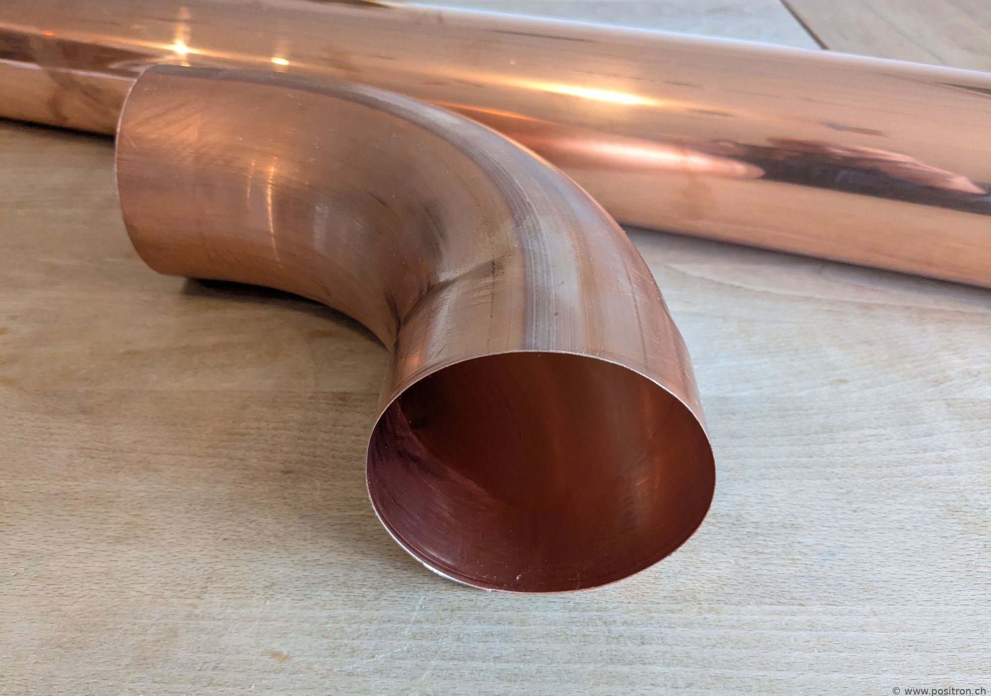
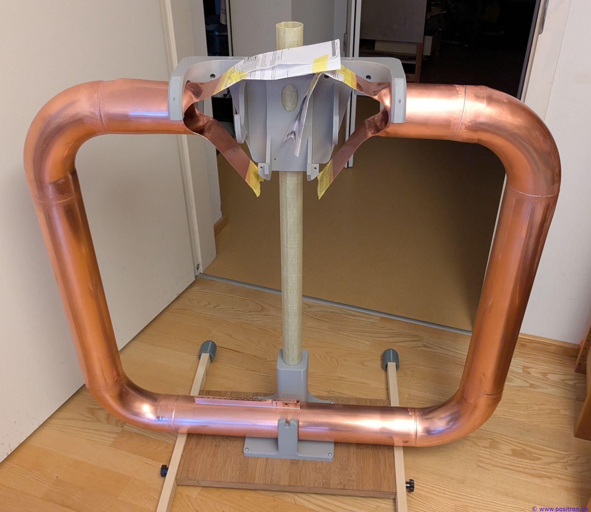
Copper tube with 100 mm outer diameter. Pre-made bends with an 85° angle are available; with a bit of forcing a 90° angle can be achieved.
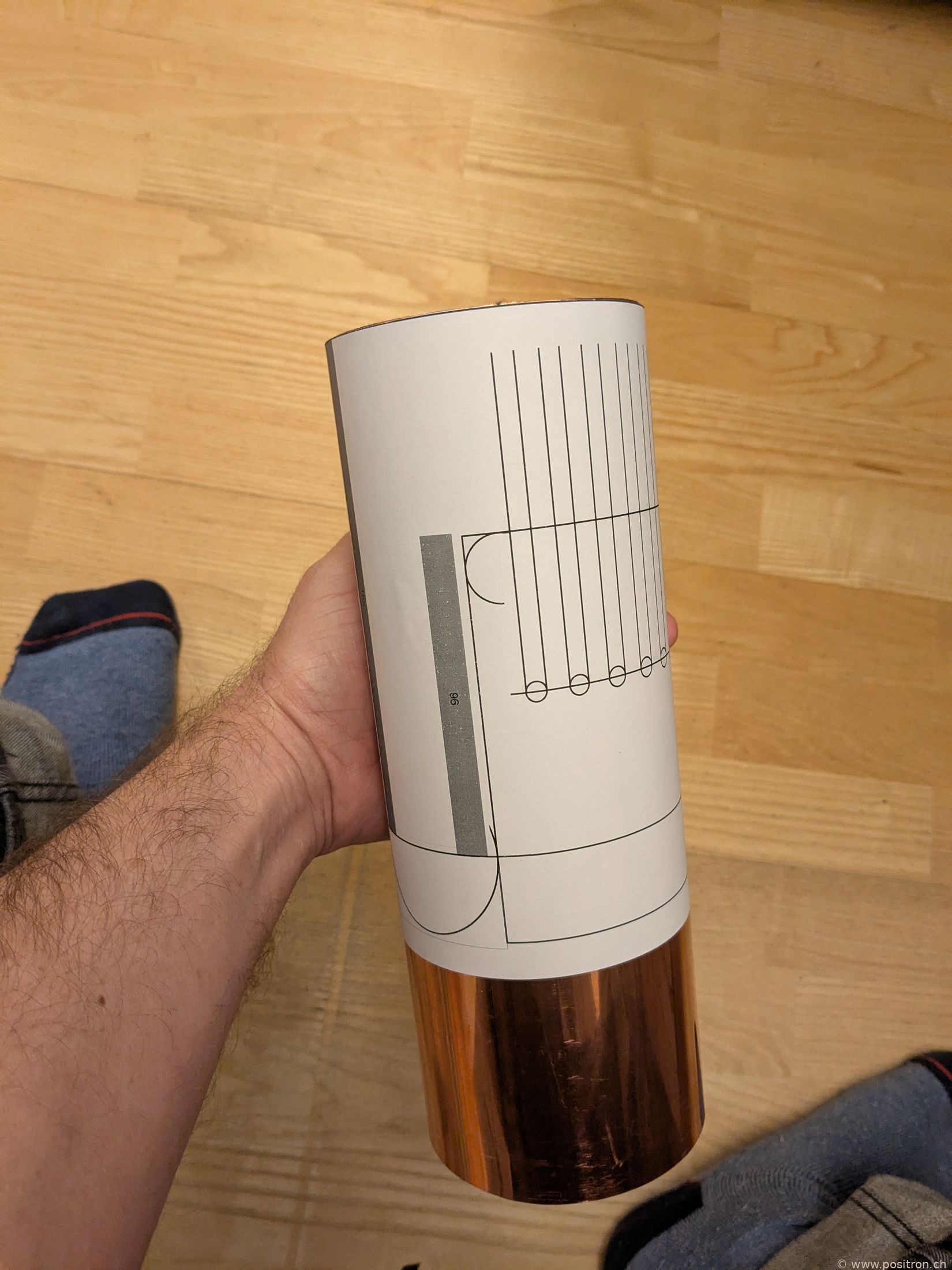
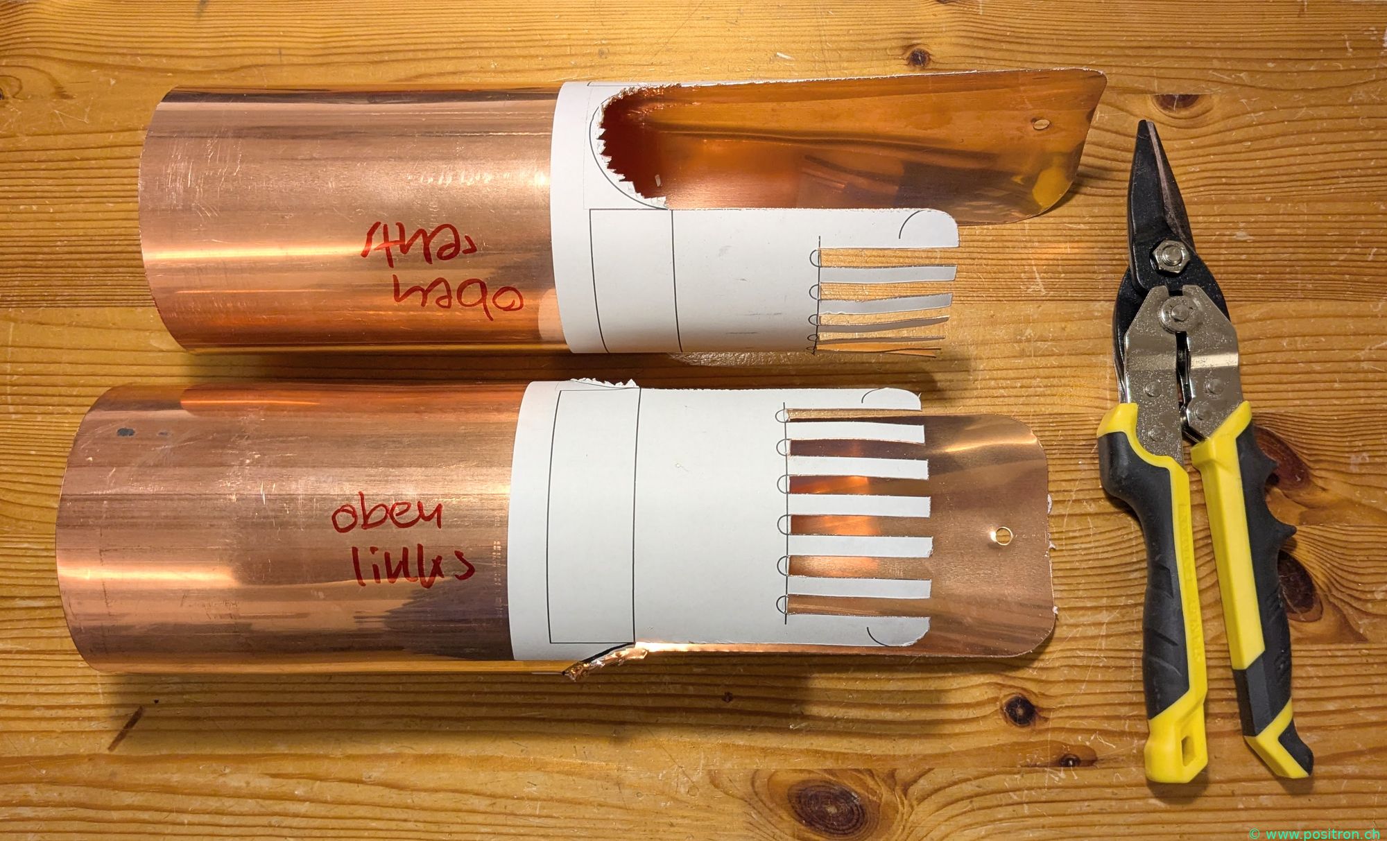
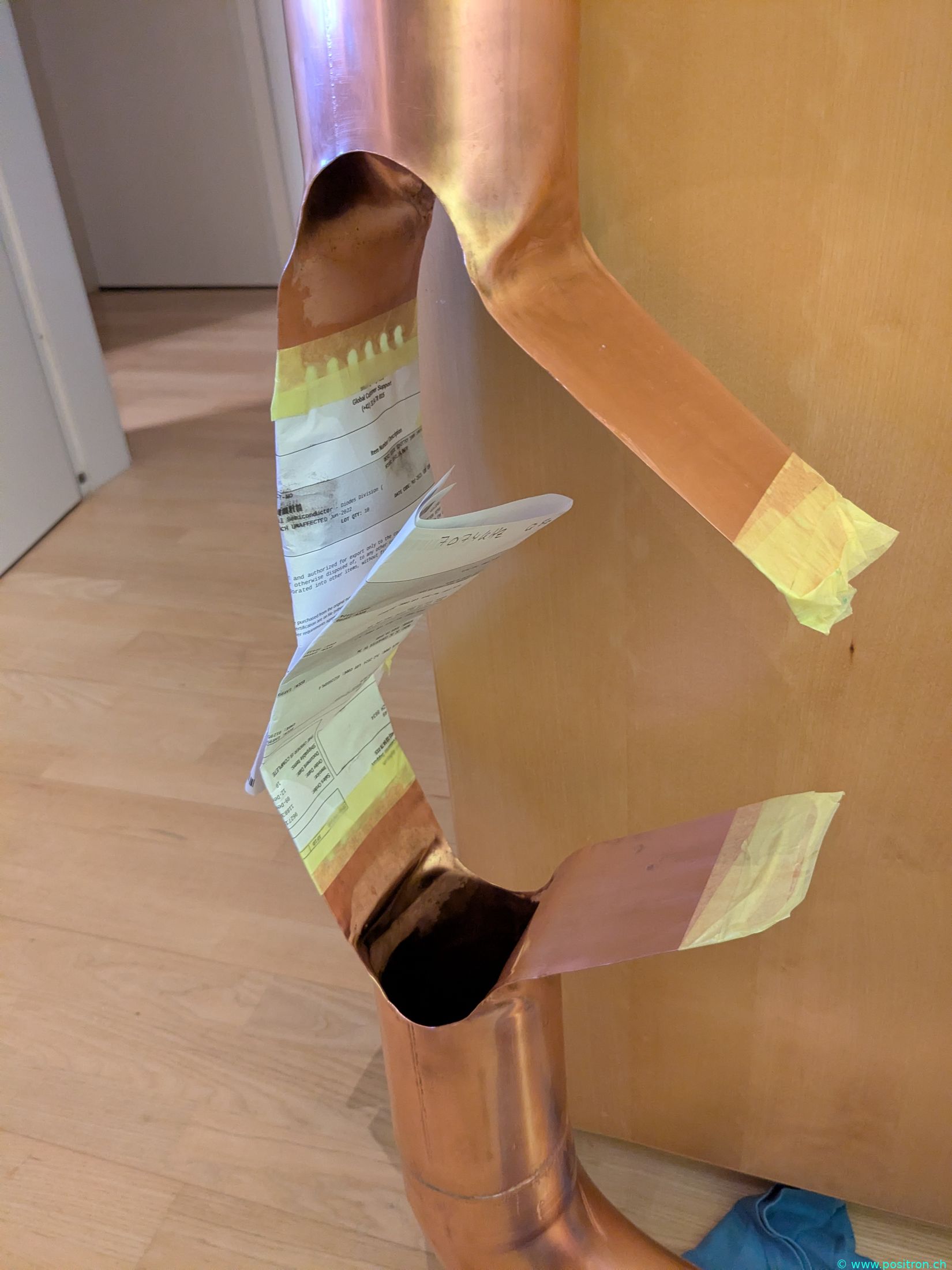
Pattern glued on.
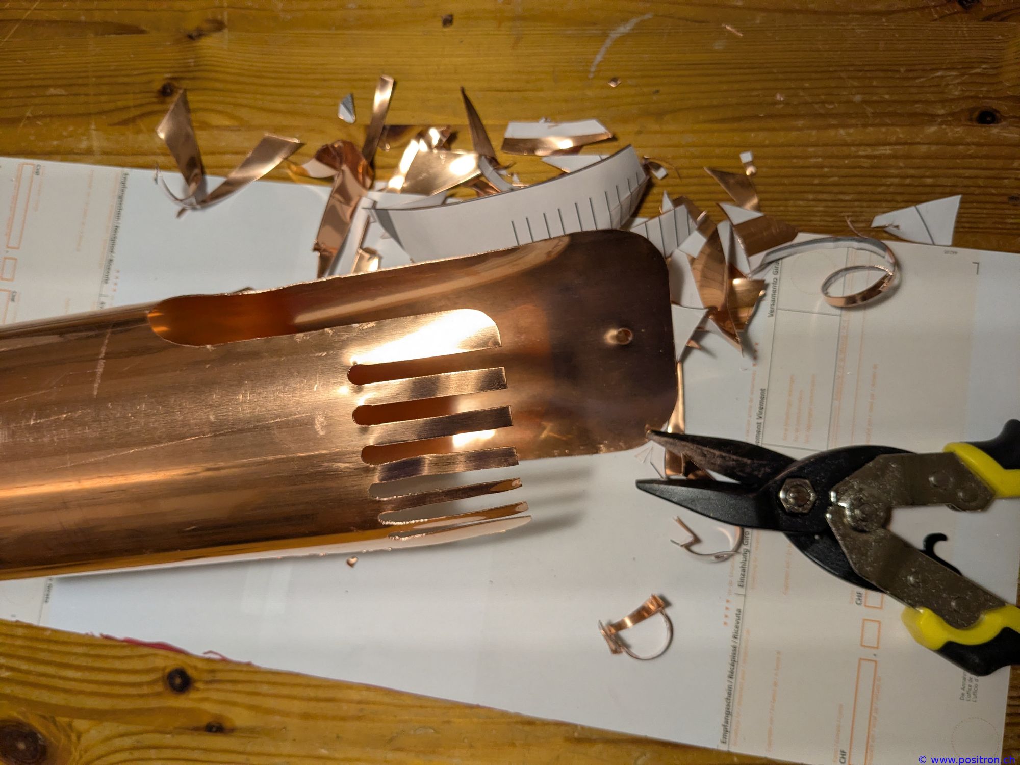
Cut with tin snips.
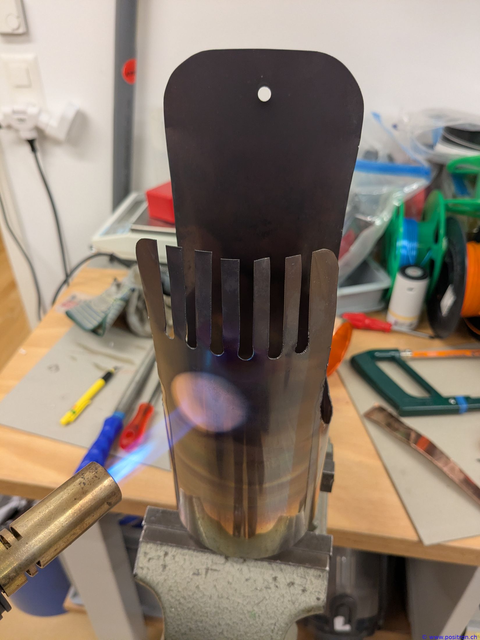
Annealing the copper to soften it.
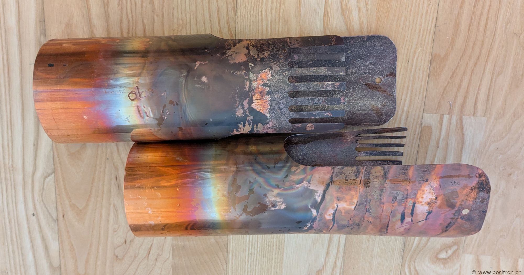
Annealing oxidises the surface.
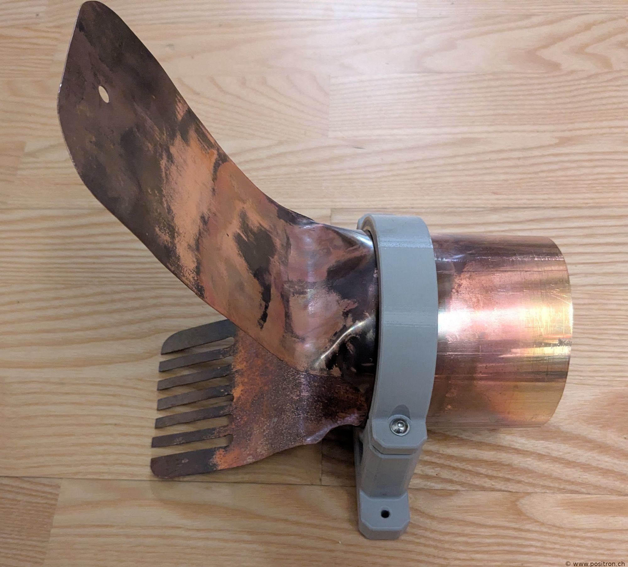
Bending the tabs.
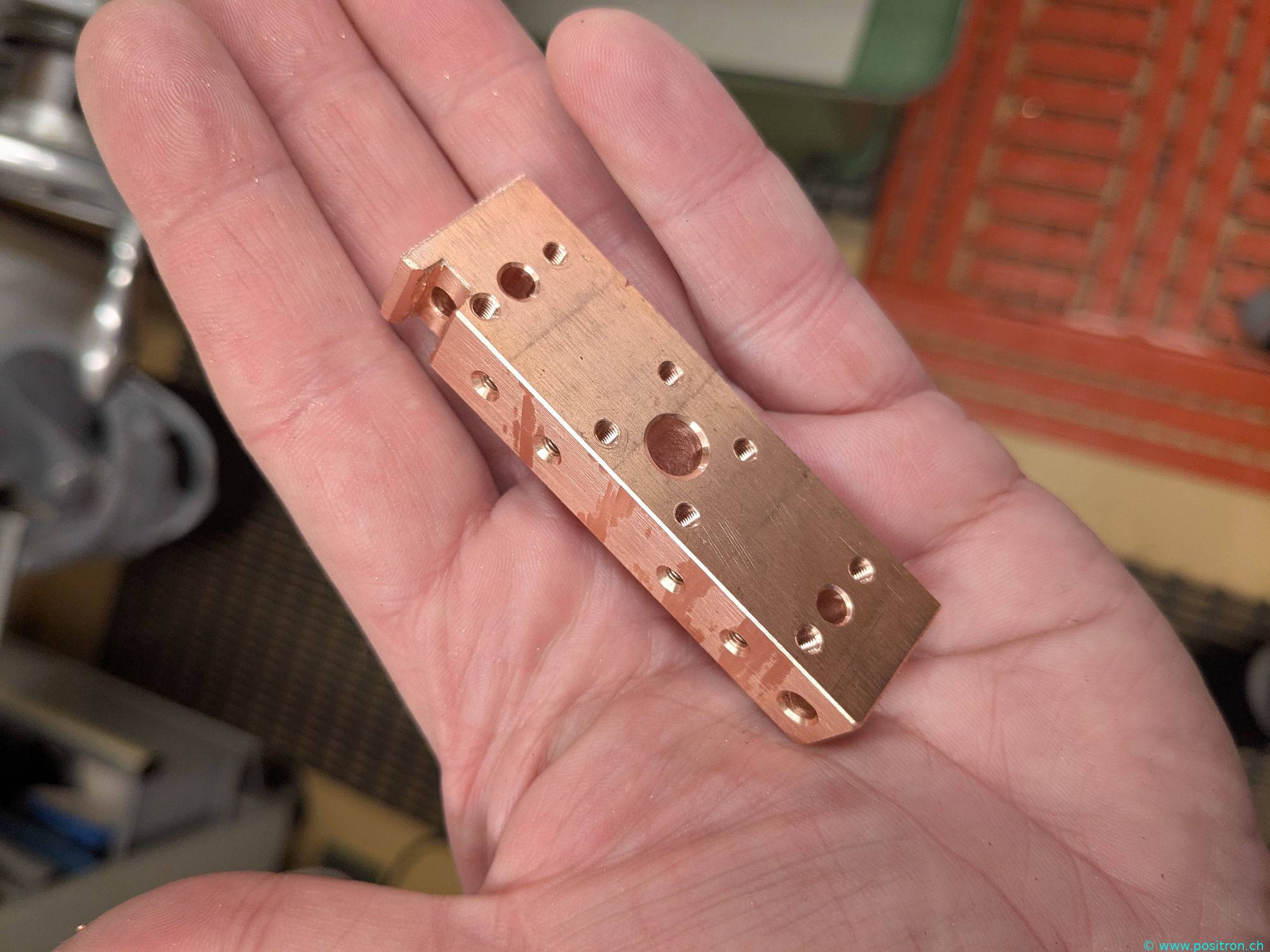
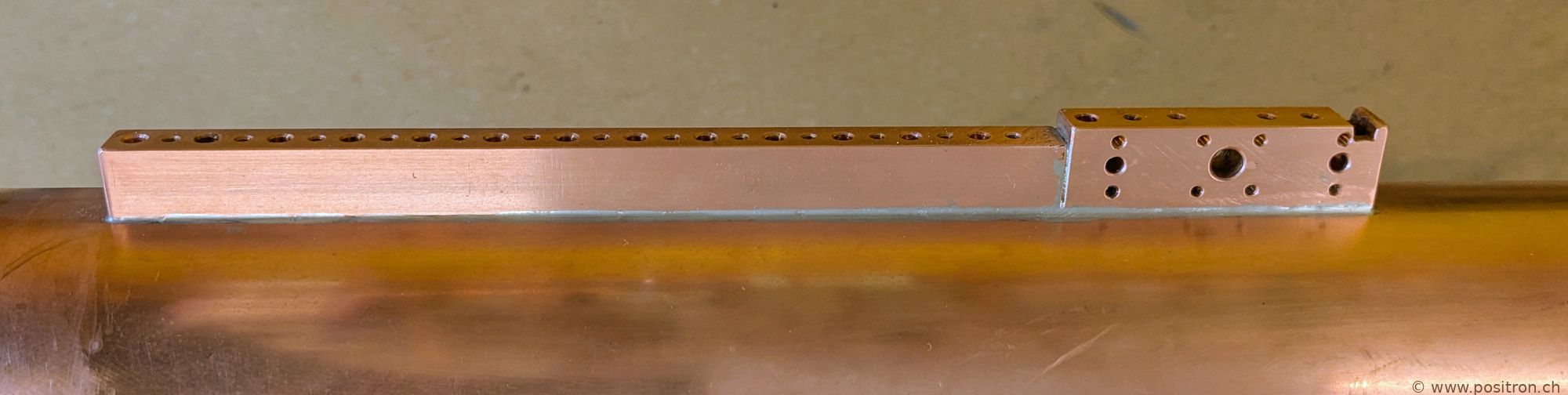
Milled contact block from OF copper. The N-type connector will be attached here later.
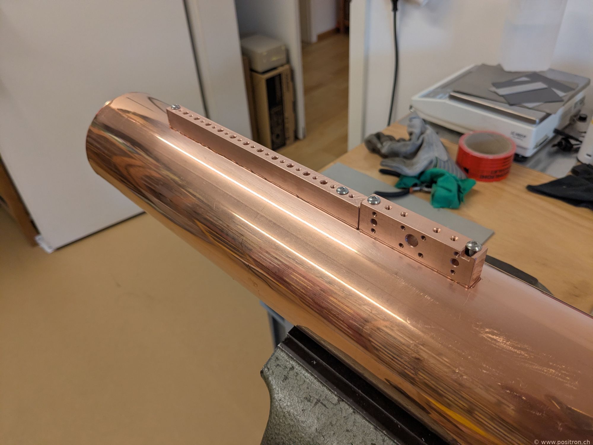
The contact blocks are bolted to the tube.
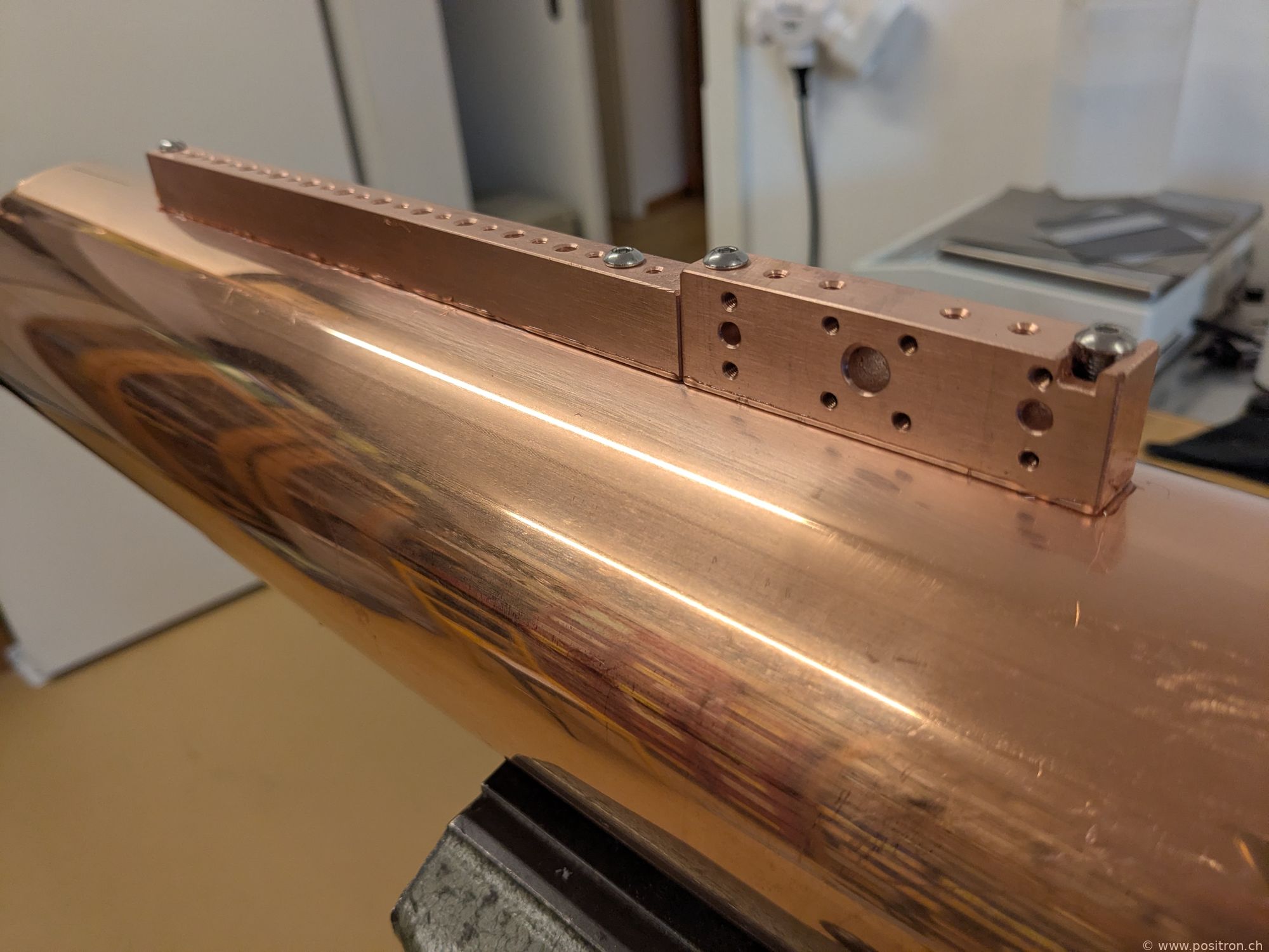
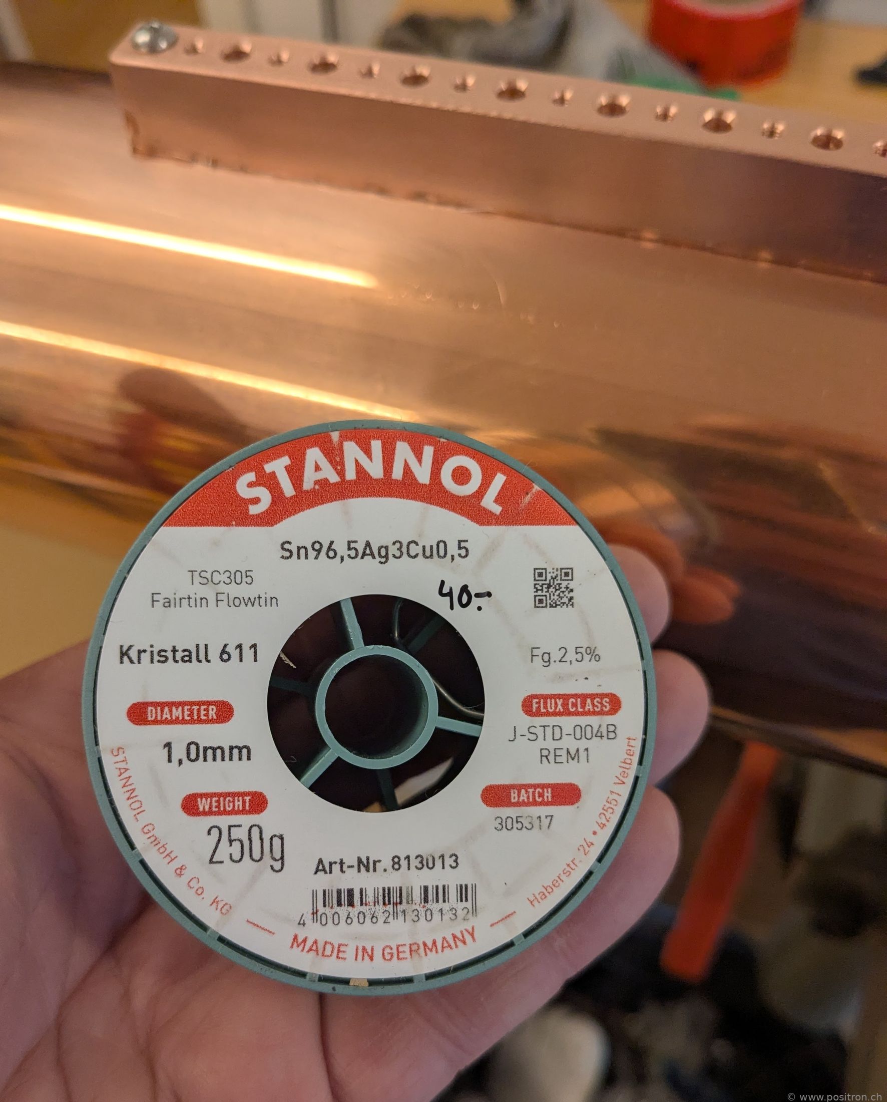
The soft solder contains silver.
The joints are clamped together with stainless steel hose clamps. The solder joint should be thin. Cord is used to pull the tube sections into position. The bends are only 85°, but 90° is needed.
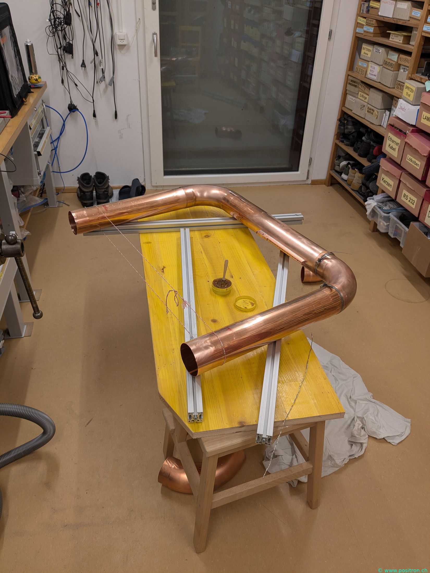
Flux has been applied.
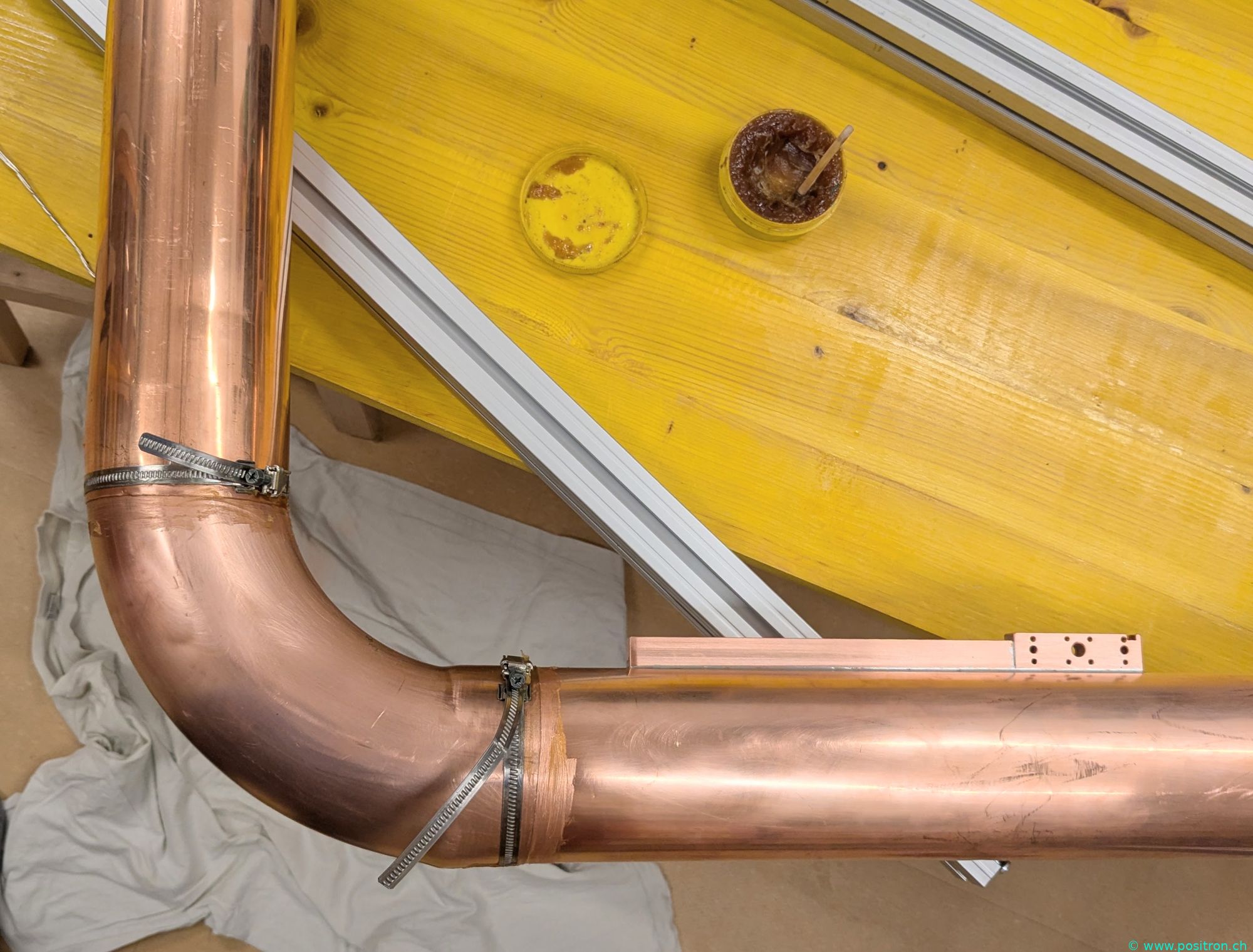
After soldering with the blowtorch. The solder flows nicely. Lower centre: a cut in the outer tube allows it to be drawn together with the hose clamp.
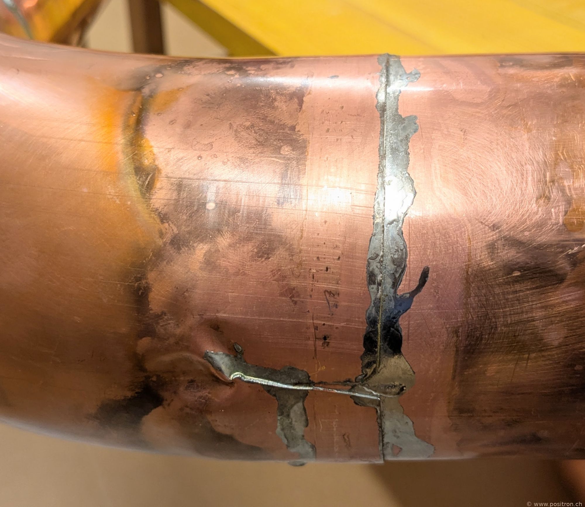
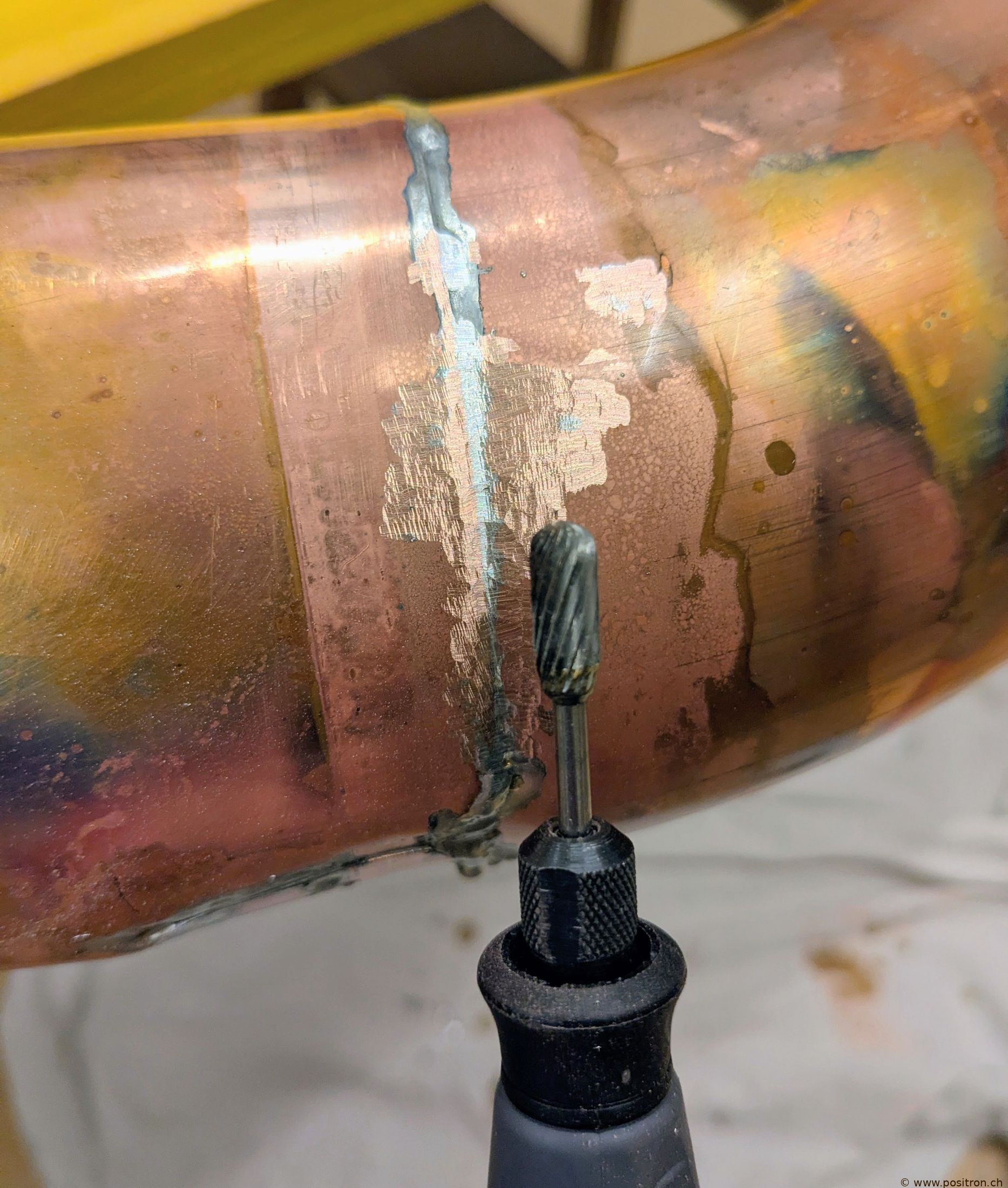
The excess solder is milled away with a Dremel. The chips were very sharp and fine and stuck everywhere, including in the skin. Due to the fine chips I would not do this again.
In the bathtub I polish the surface with steel wool and soap. It is hard work. The abrasion is deep black.
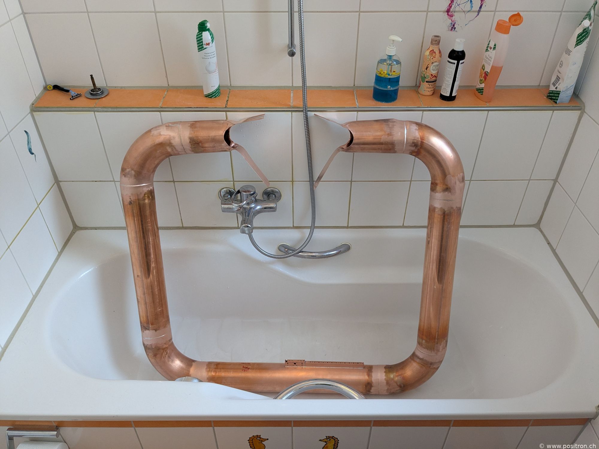
Contact blocks.
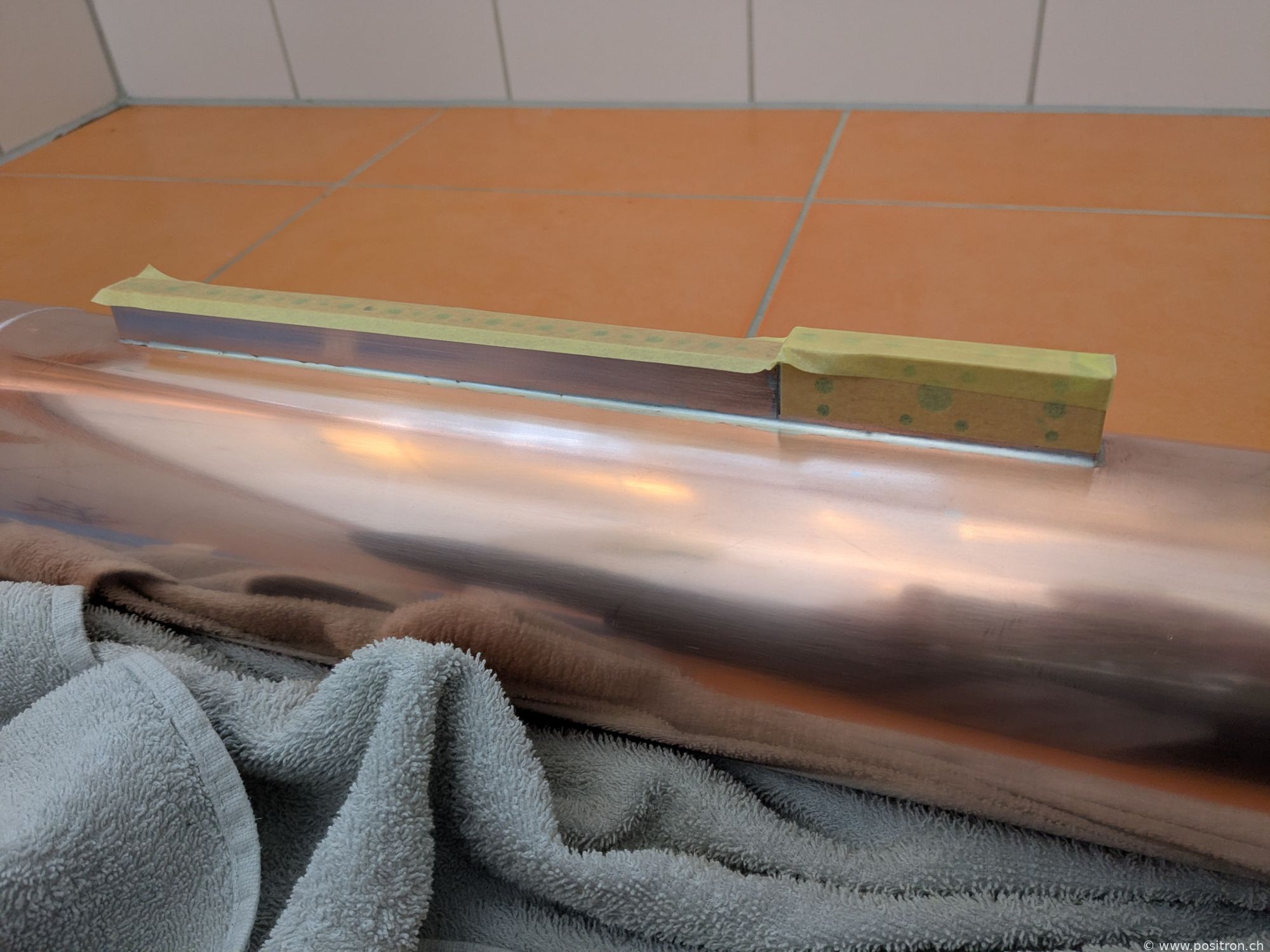
Degrease, mask off parts not to be lacquered.
Masking the contacts.
Applying transparent protective lacquer "PLASTIK 70".
Lacquering complete. It shines.
Contacts bolted with M6 screws to the variable capacitor.
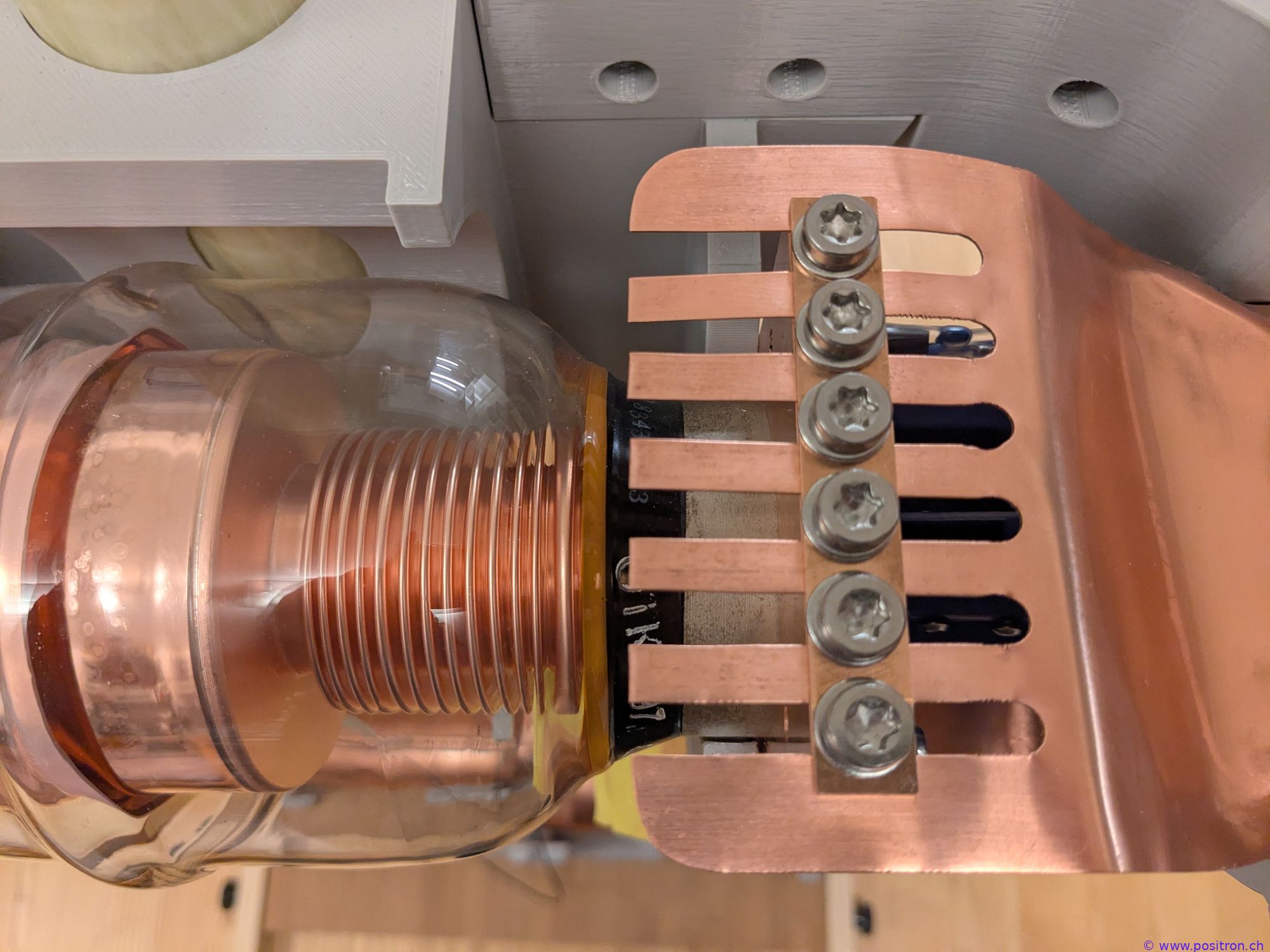
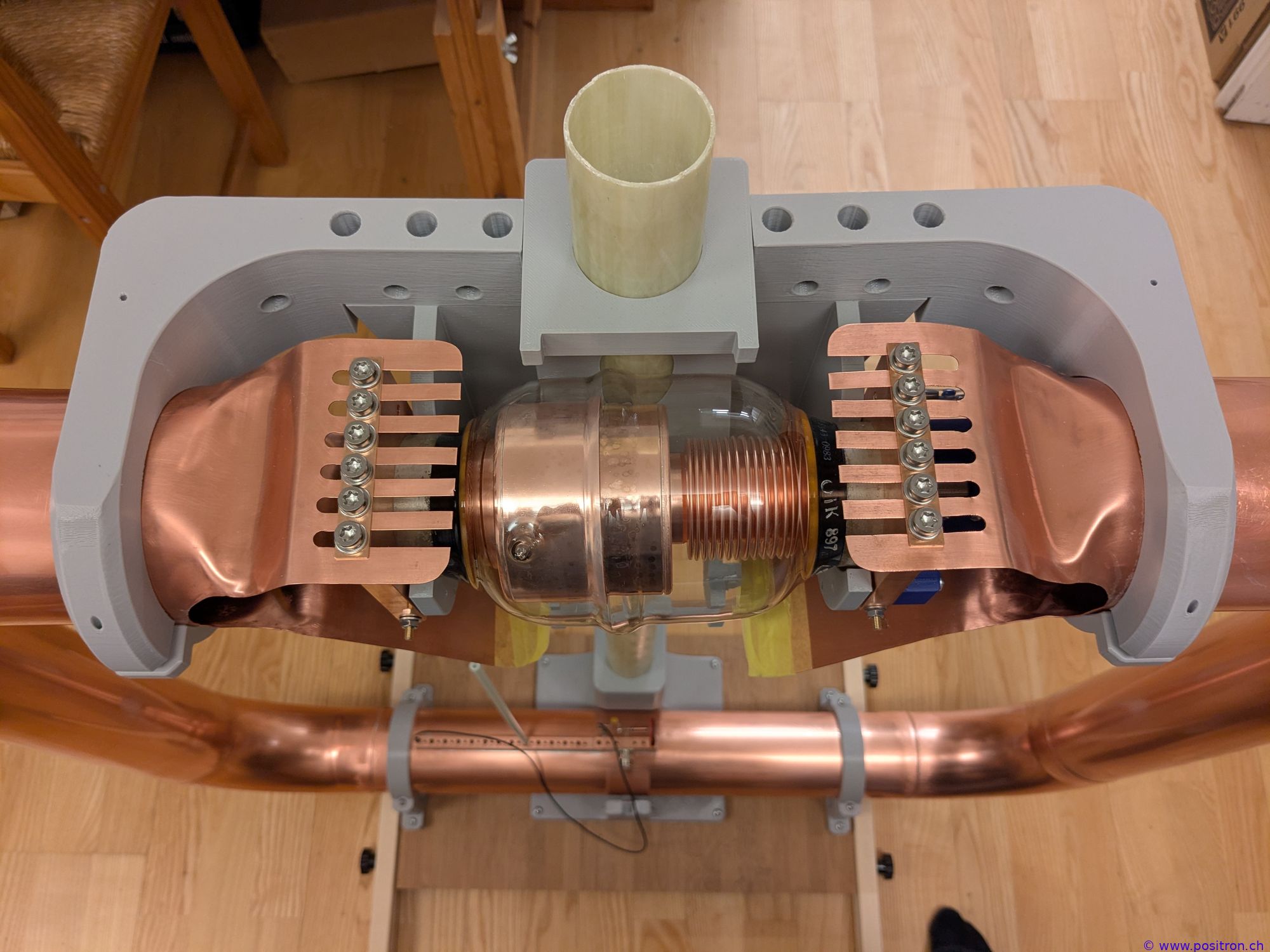
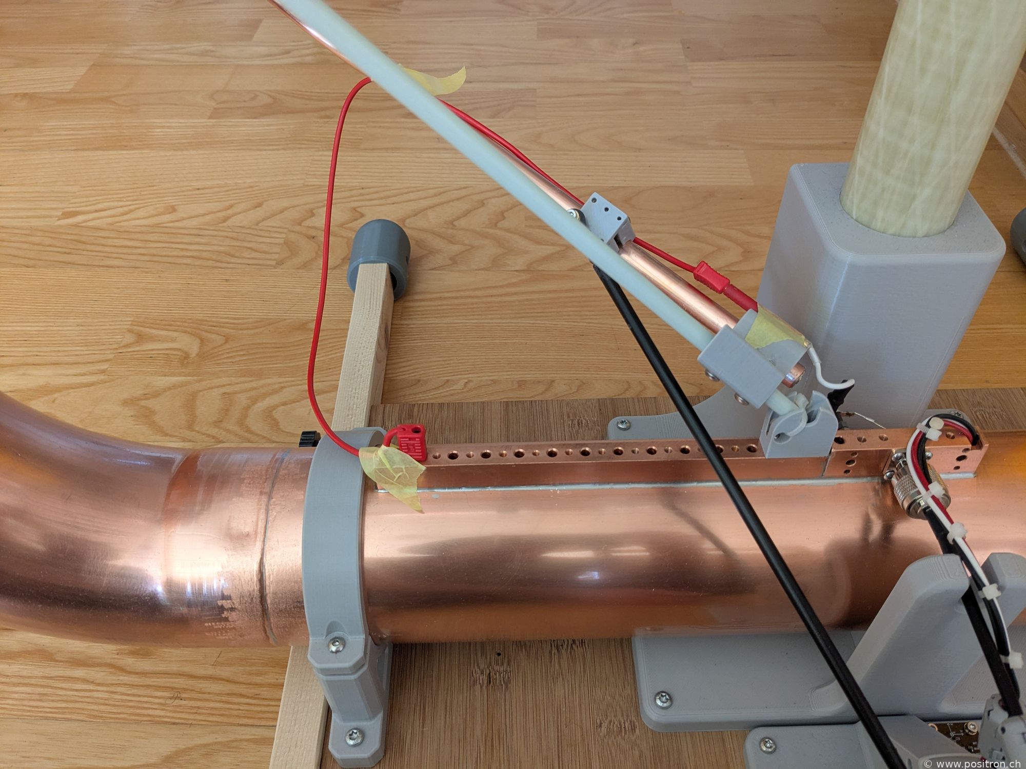
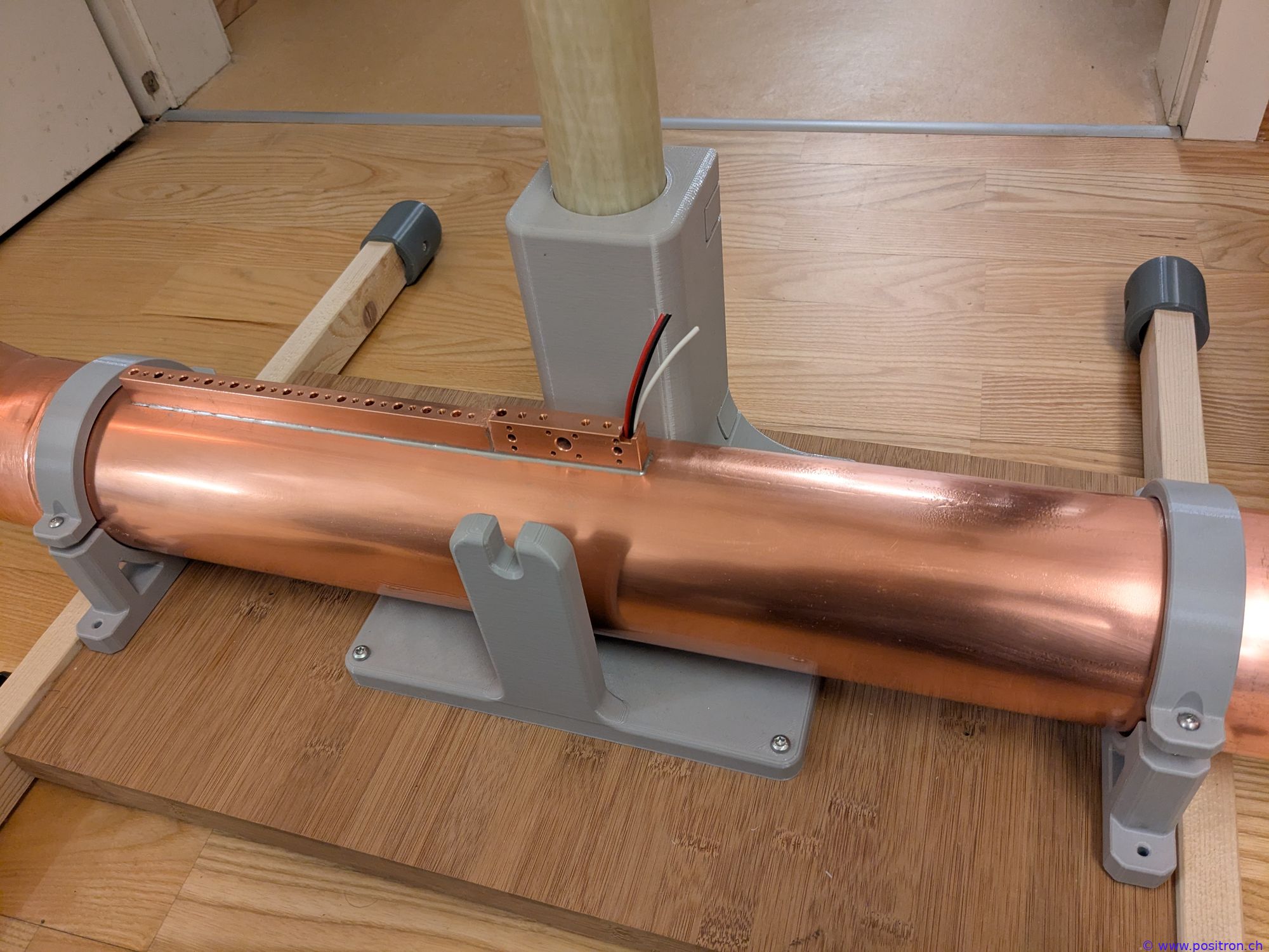
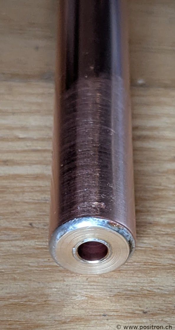
Gamma match loop made from copper tube with 12 mm outer diameter.
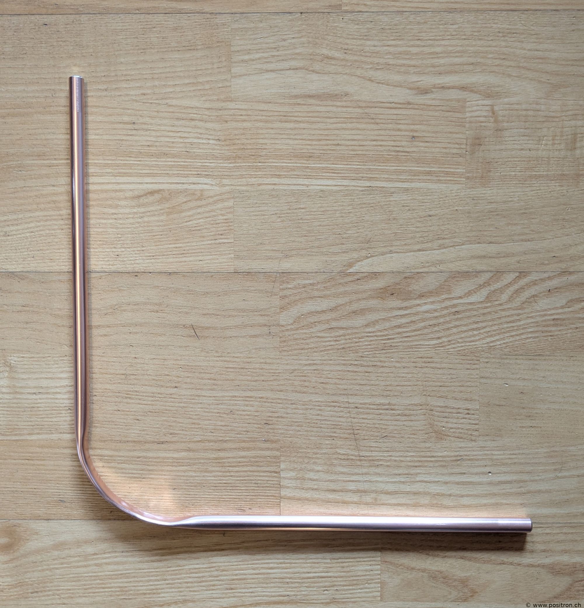
End with a soldered-in 4 mm banana socket.
First version: coupling onto the gamma match via a 220 nF capacitor.
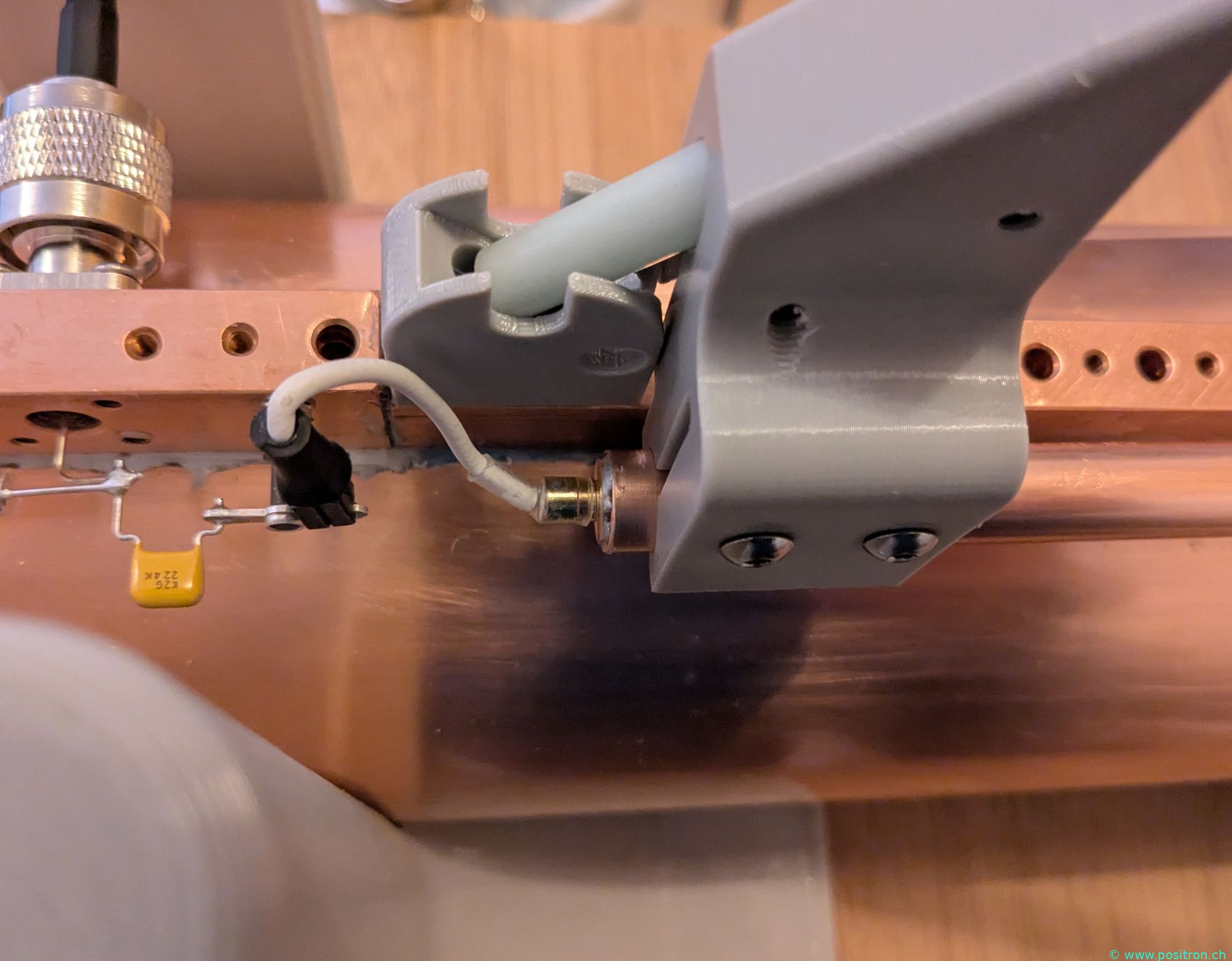
Connection from the gamma match to the loop.
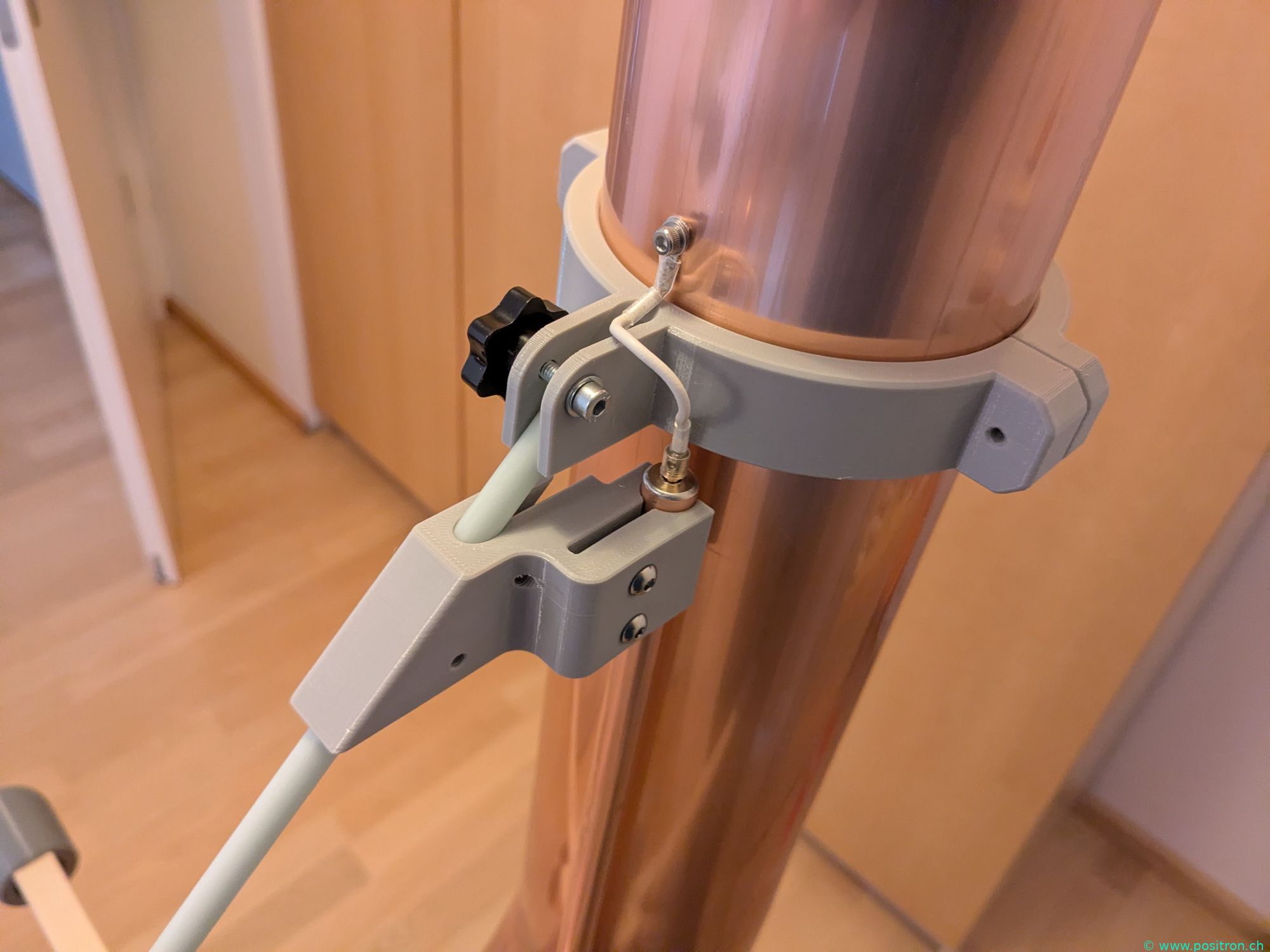
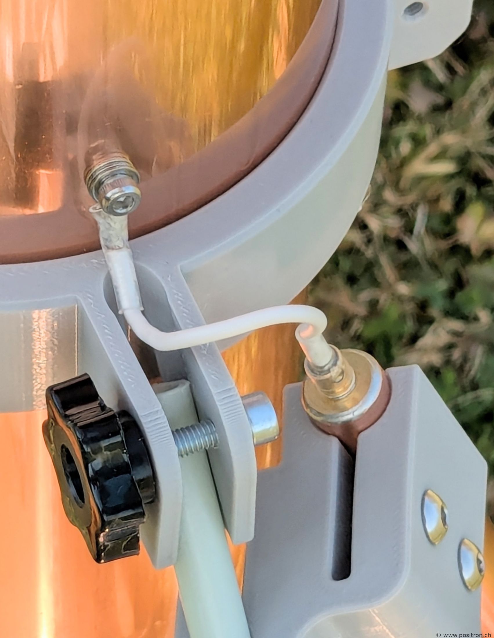
Detail view of the gamma match in position for minimum coupling.
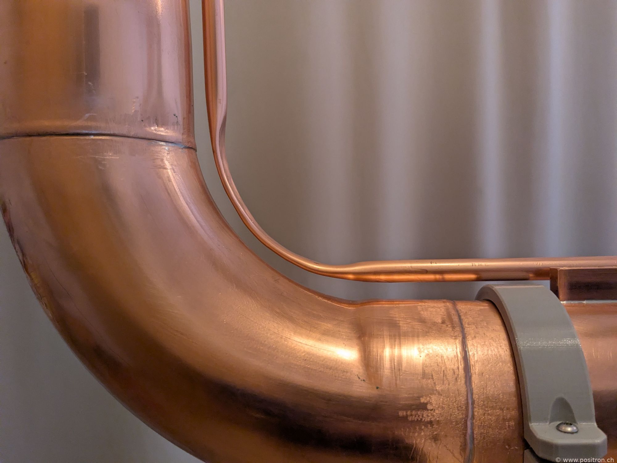
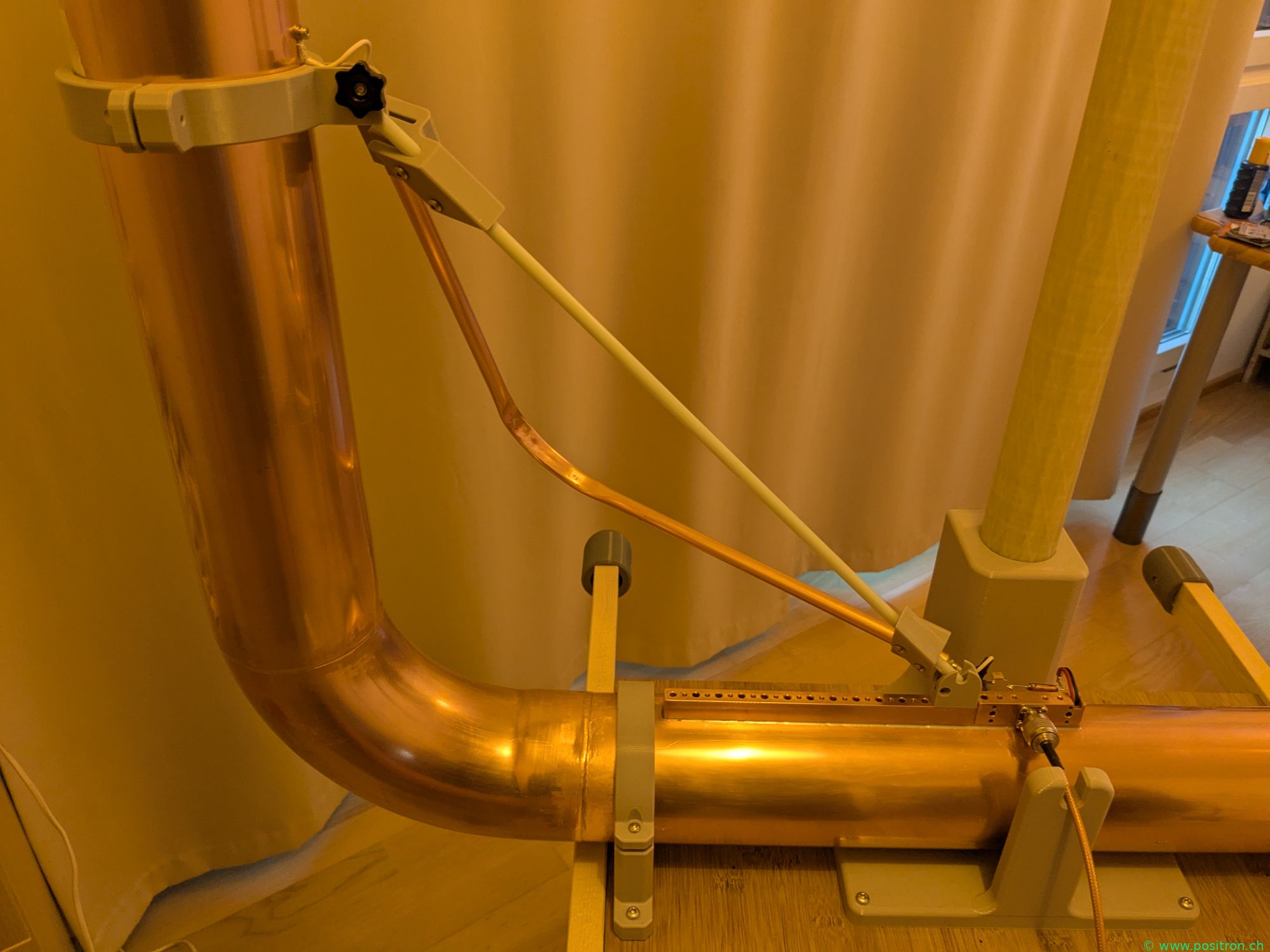
Gamma match with greater coupling.
Comet Vacuum Capacitors
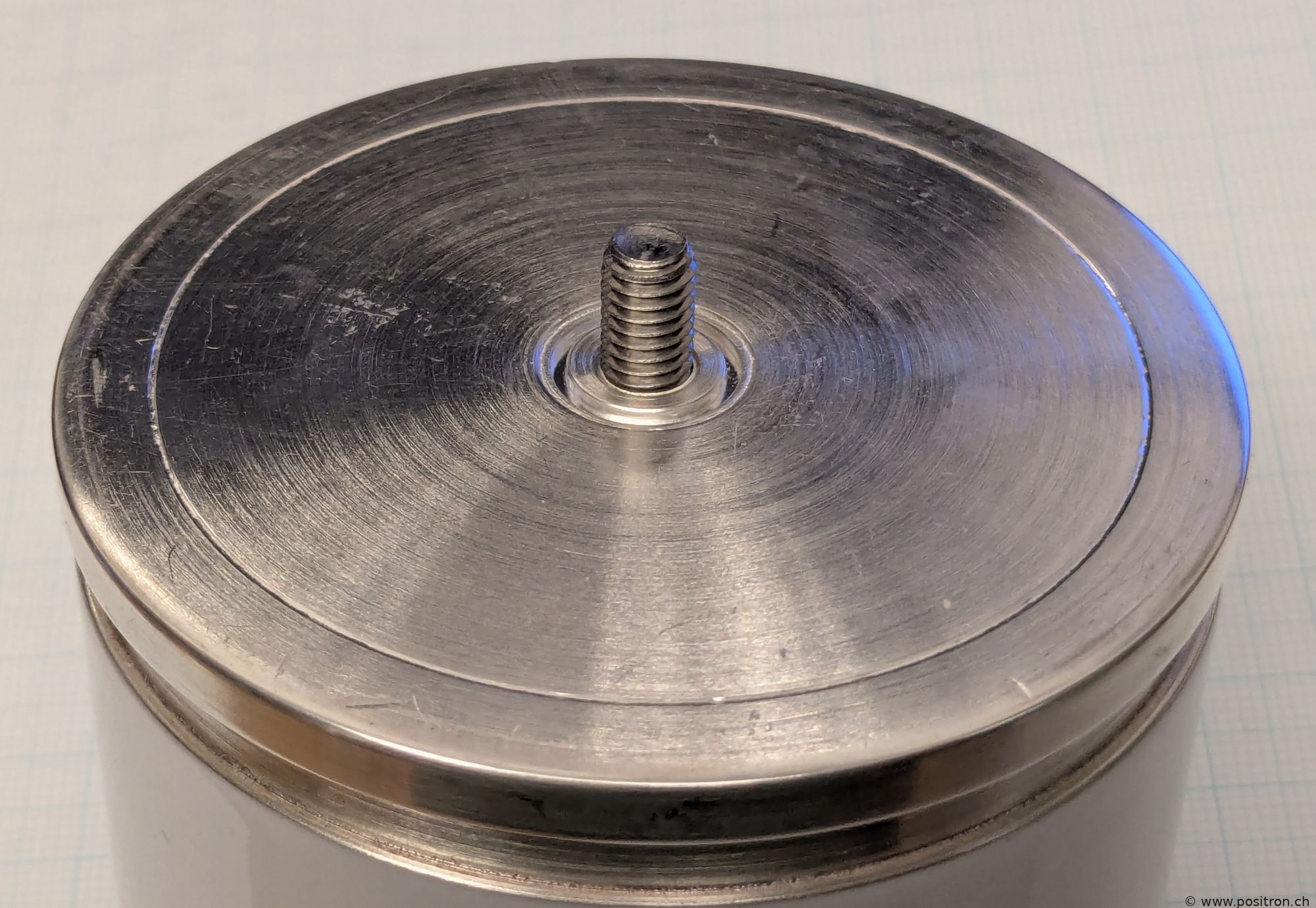
Vacuum capacitor with M6 grub screw.
Punching a hole in the connecting plate with a toggle press.
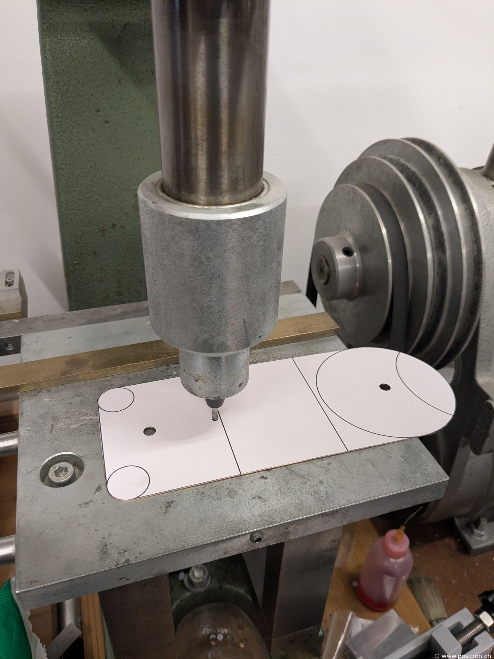
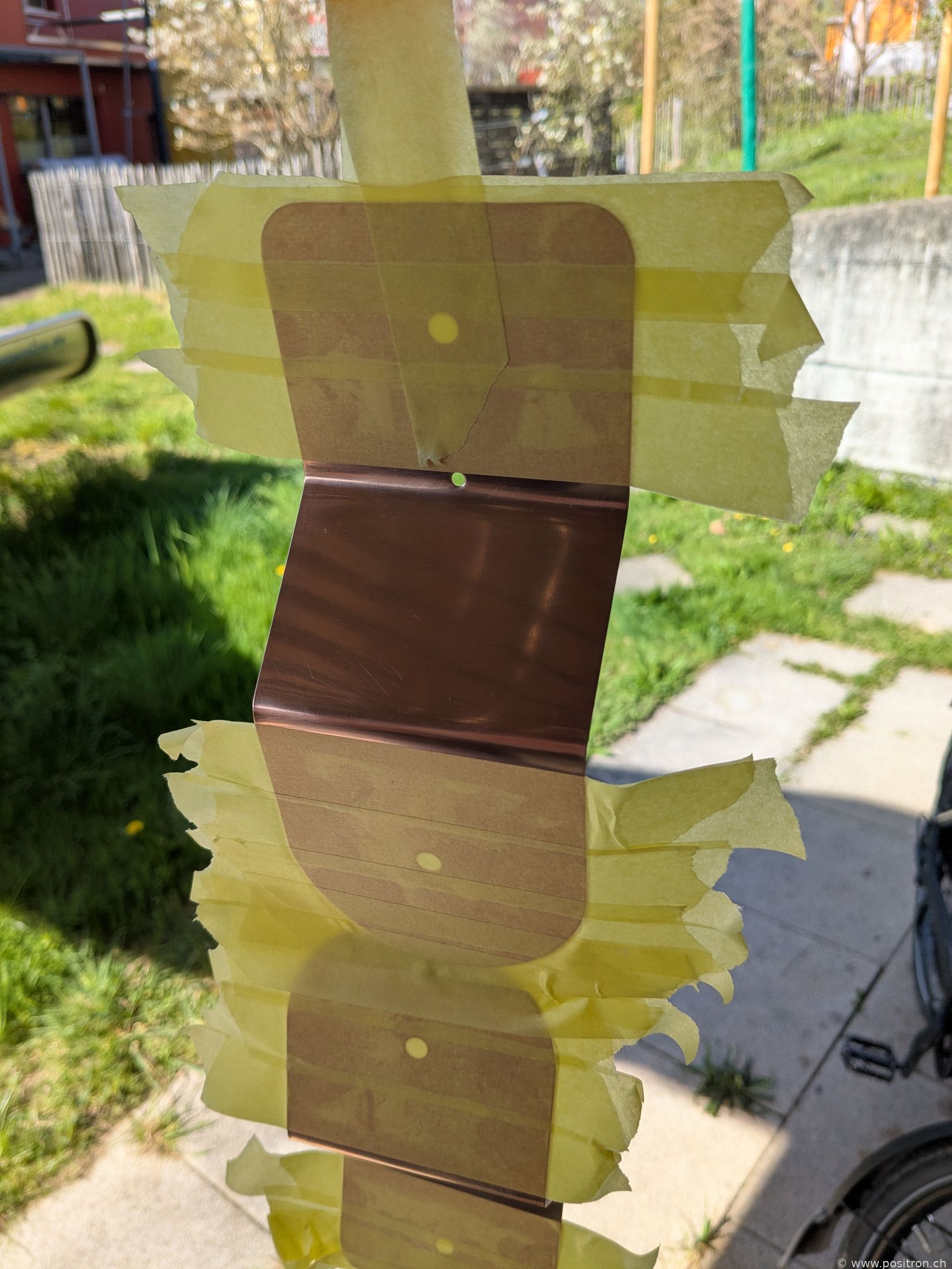
Finished polished connecting plates hung up and partially masked. Freshly lacquered.
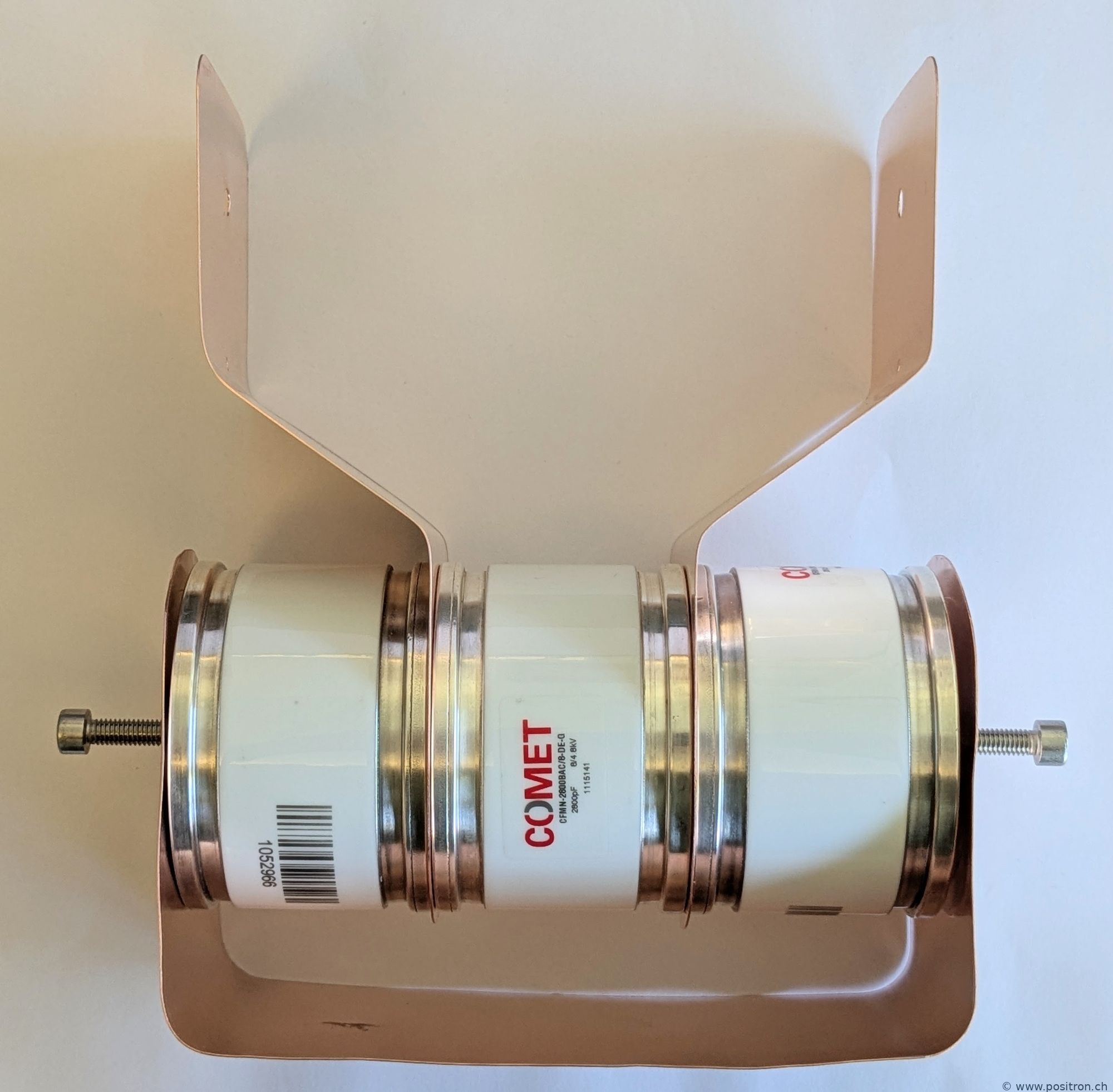
Capacitor bank with a combined capacitance of 4.2 nF.
Detail.
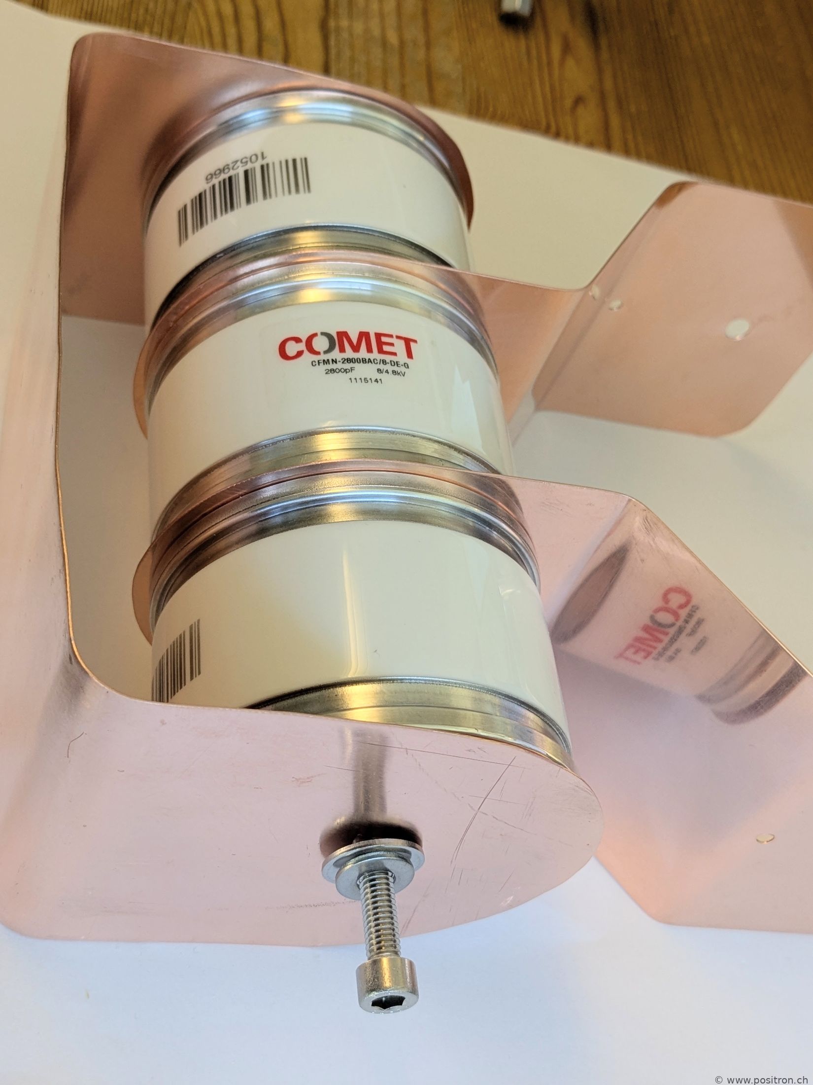
Detail.
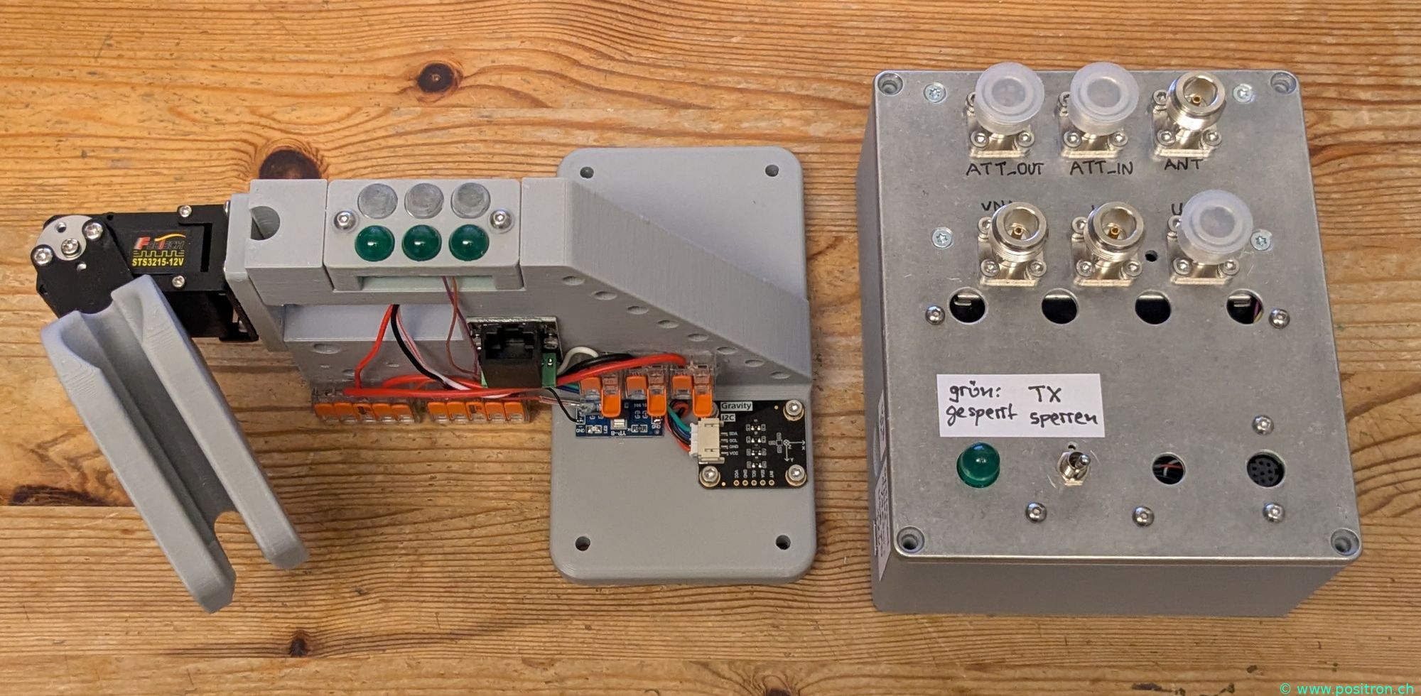
Switching box
Left: cable entry. In the first version the cable was swung by the servo. I solved this differently later. Right: the switching box.
Housing base for the switching box, 3D printed from PETG.
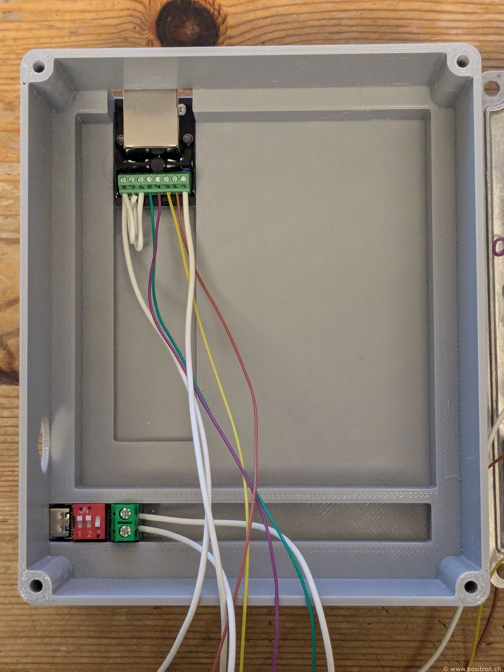
Cable entry.
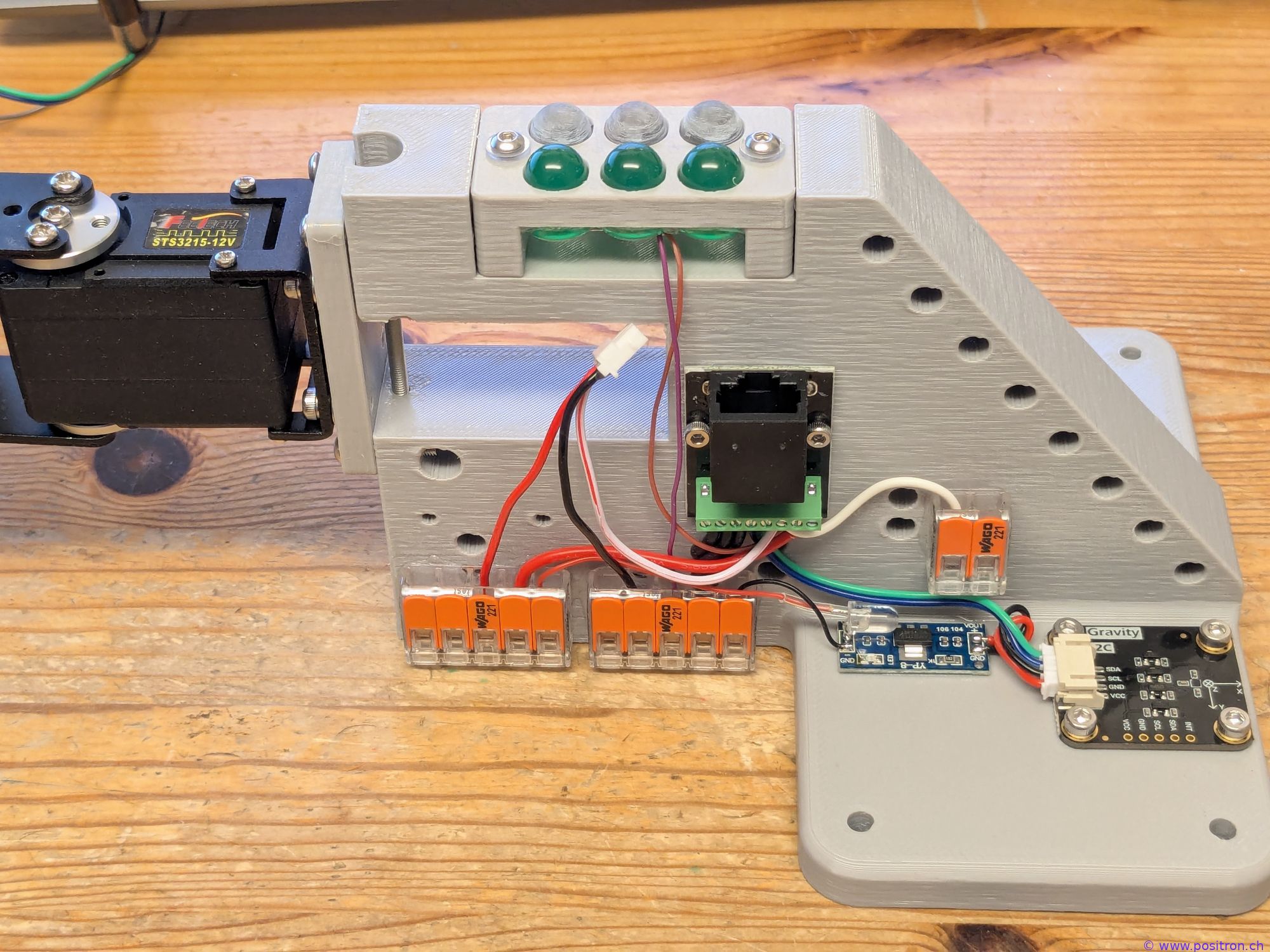
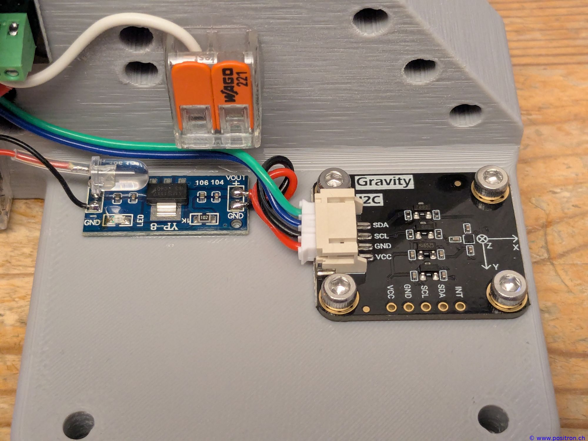
Detail view: cable entry, blue PCB voltage regulator 12 V to 3.3 V. Right: magnetometer for azimuth control.
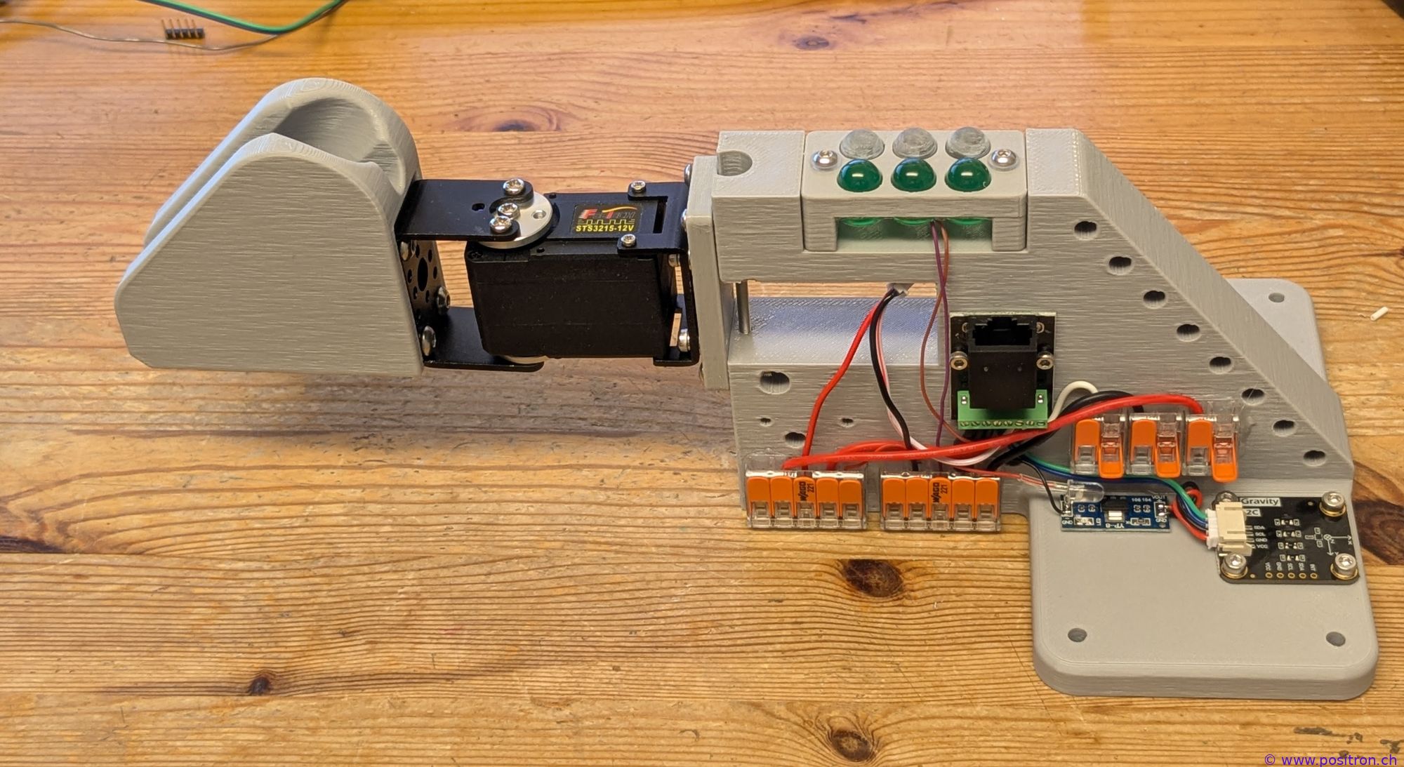
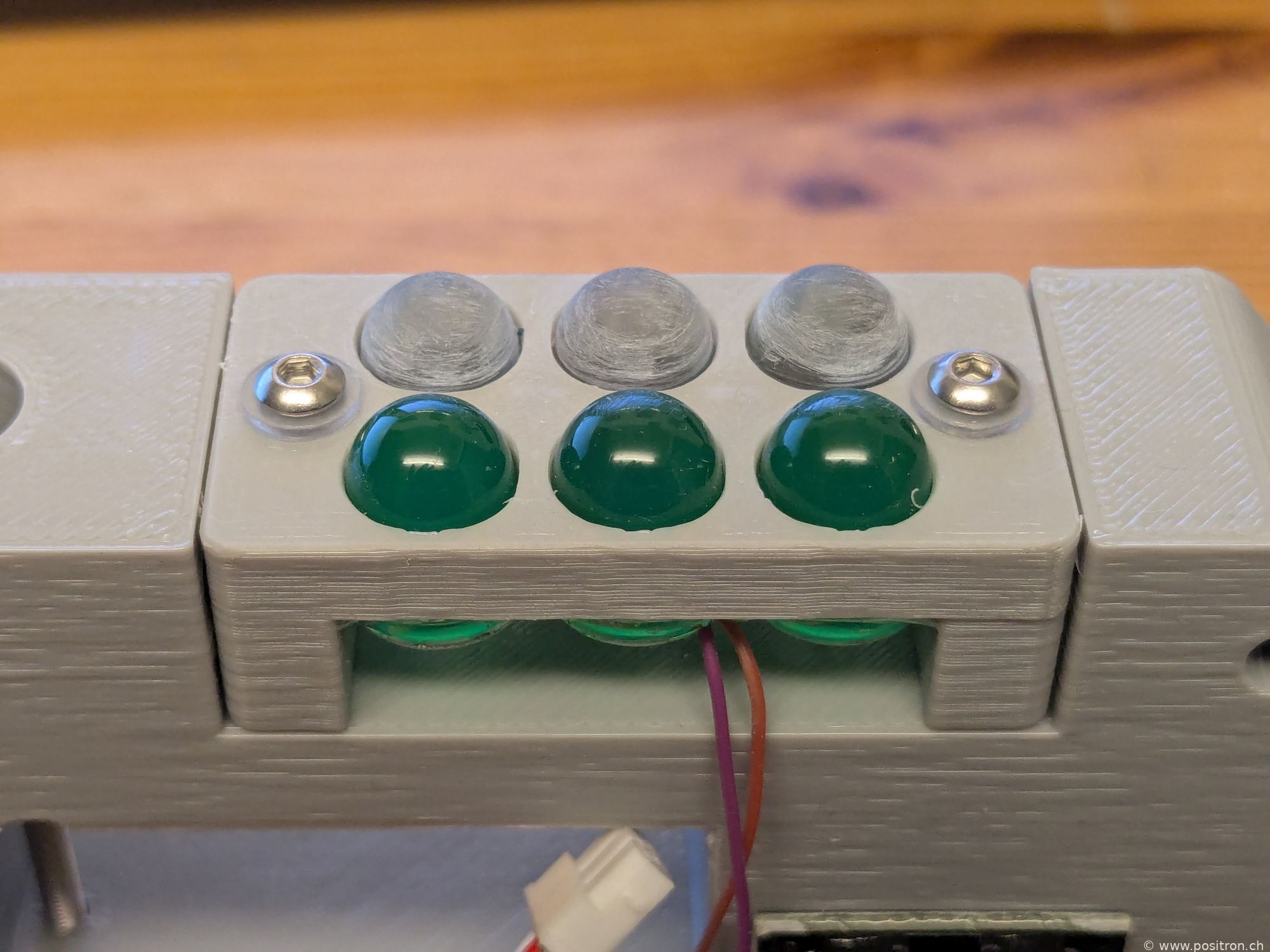
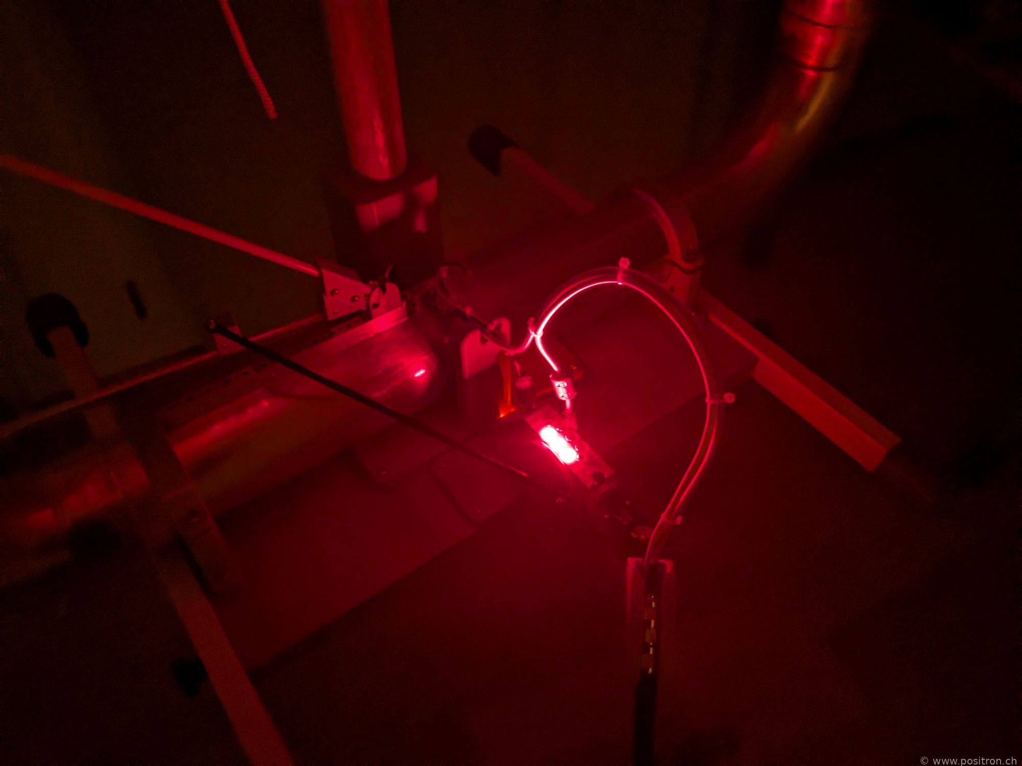
Top LED green: transmitter locked, red: transmitter unlocked – transmission could occur, keep safety distance!
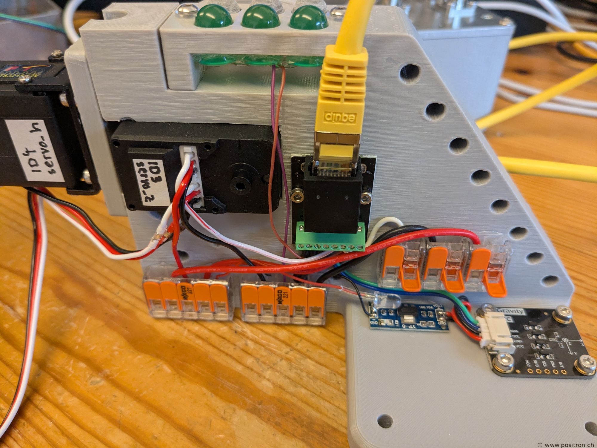
Yellow: patch cable with control signals.
Drive for the Variable Capacitor
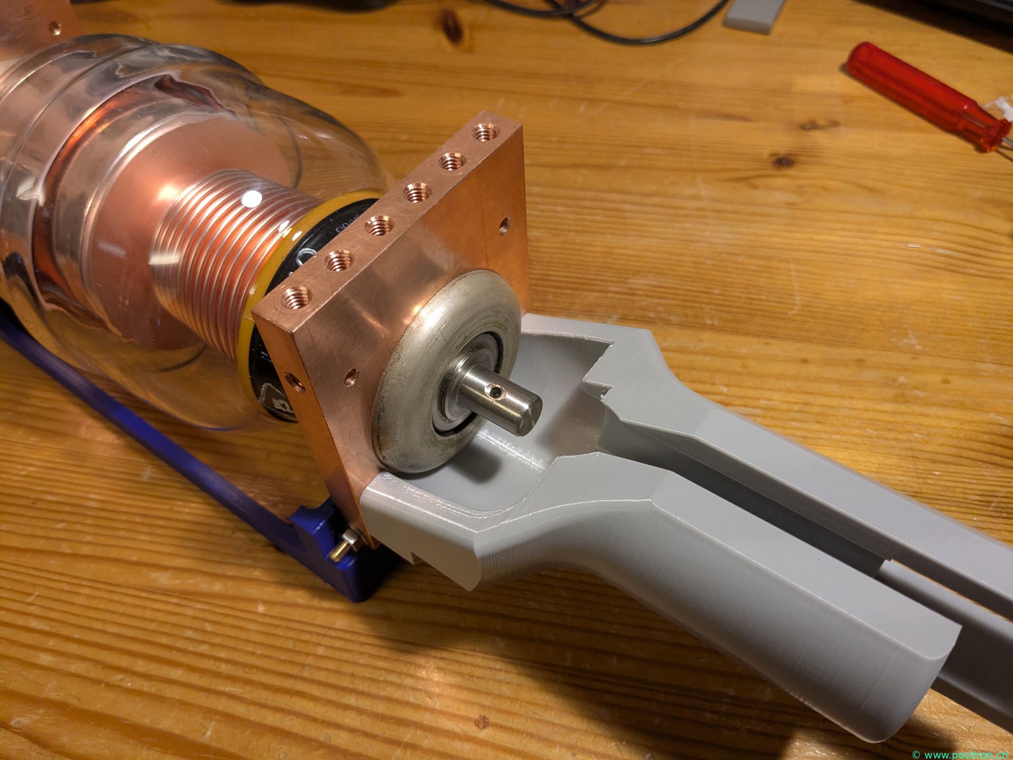
Drive for the variable capacitor. 3D printed part from PETG is bolted to the contact plate.
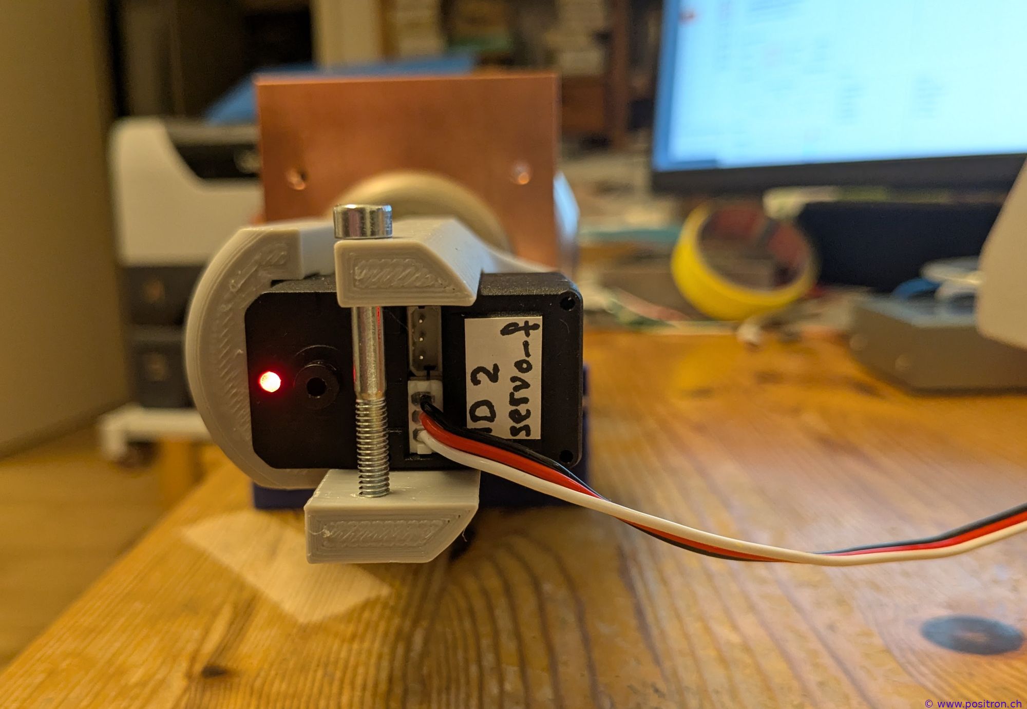
View of the servo.
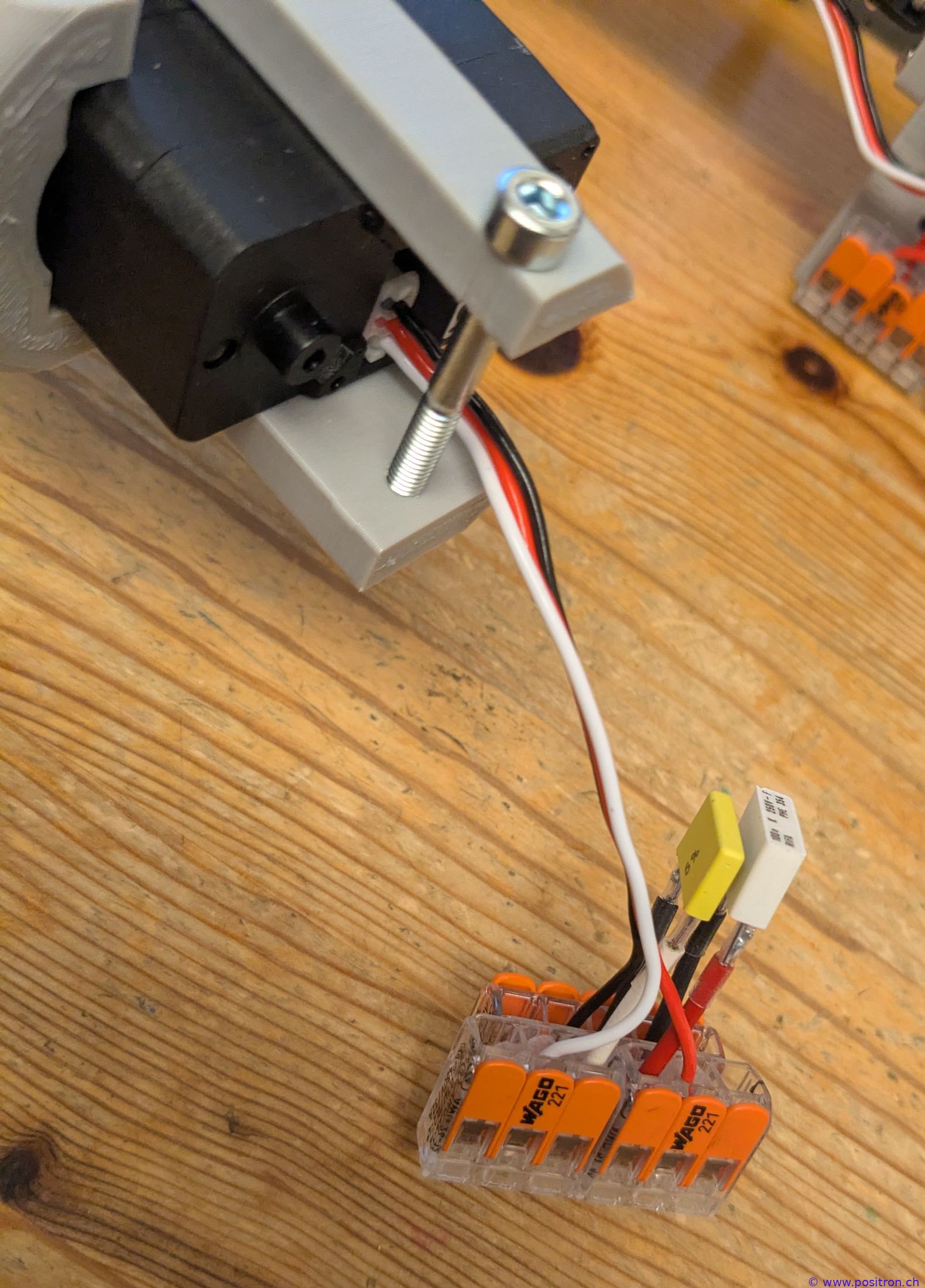
Bypass capacitors in the control line.
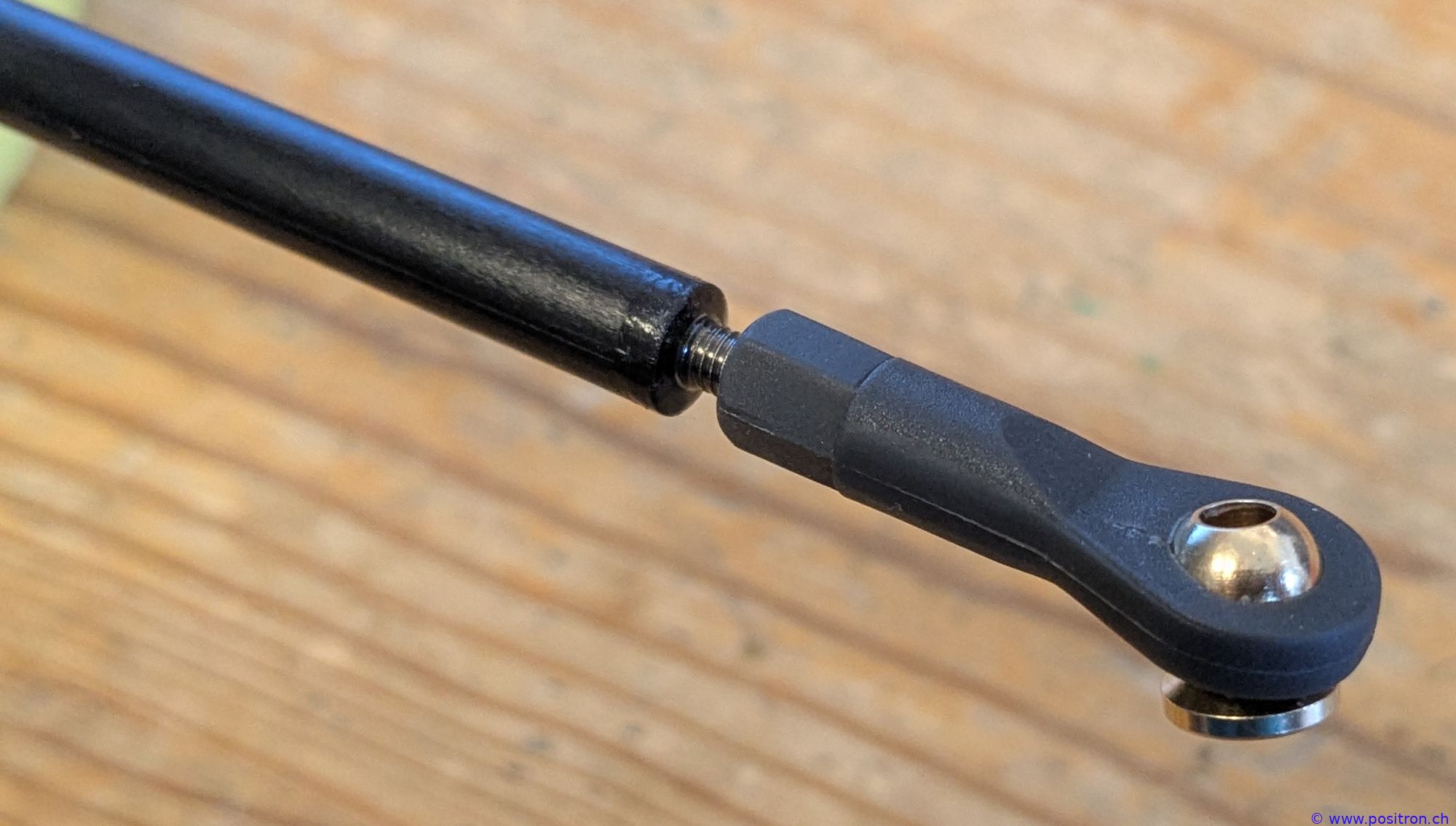
Linkage made from black fibreglass rod (not carbon fibre!). Ball head.
Drive for the Gamma Match
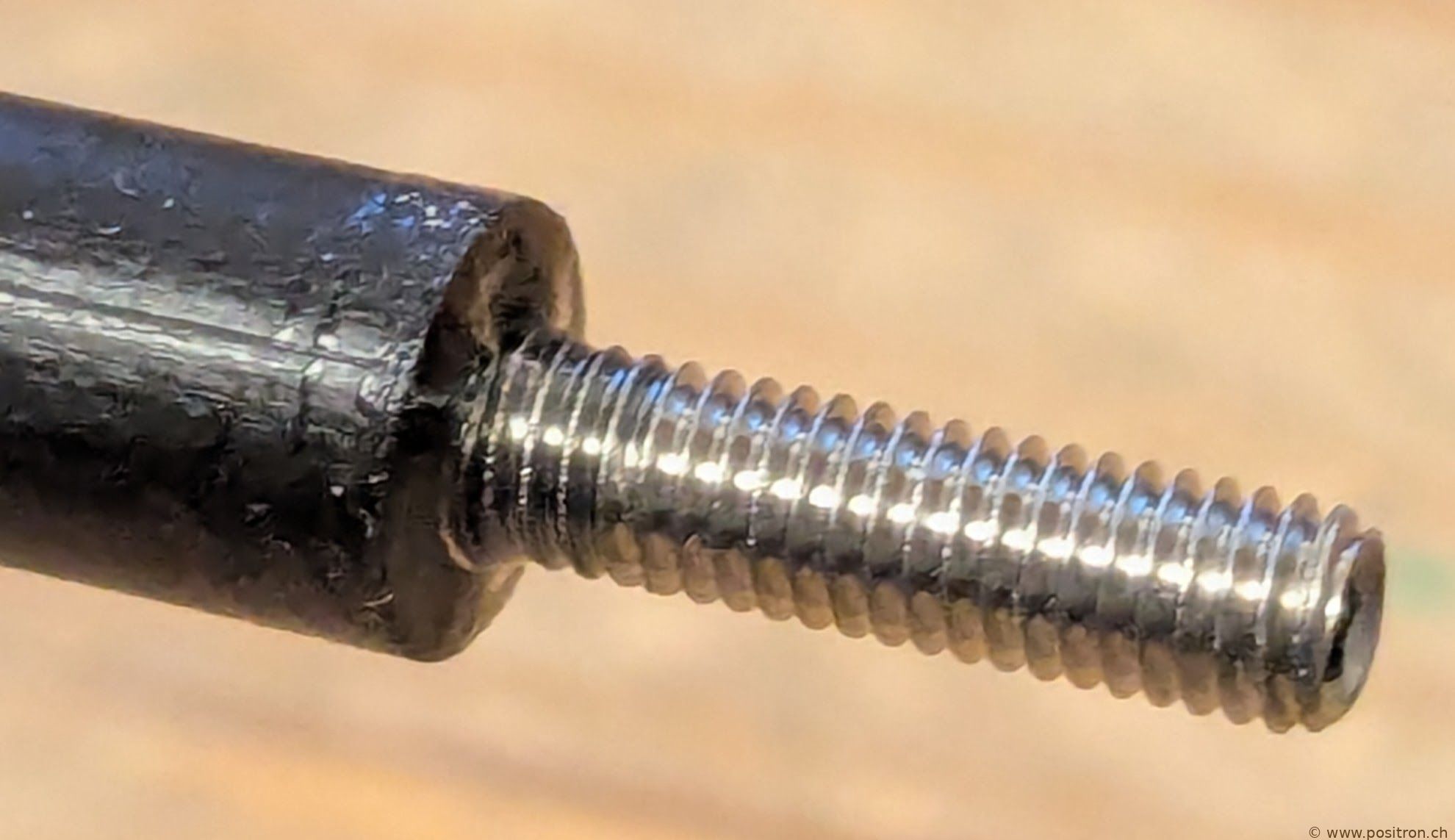
M3 A2 grub screw bonded in with epoxy resin.
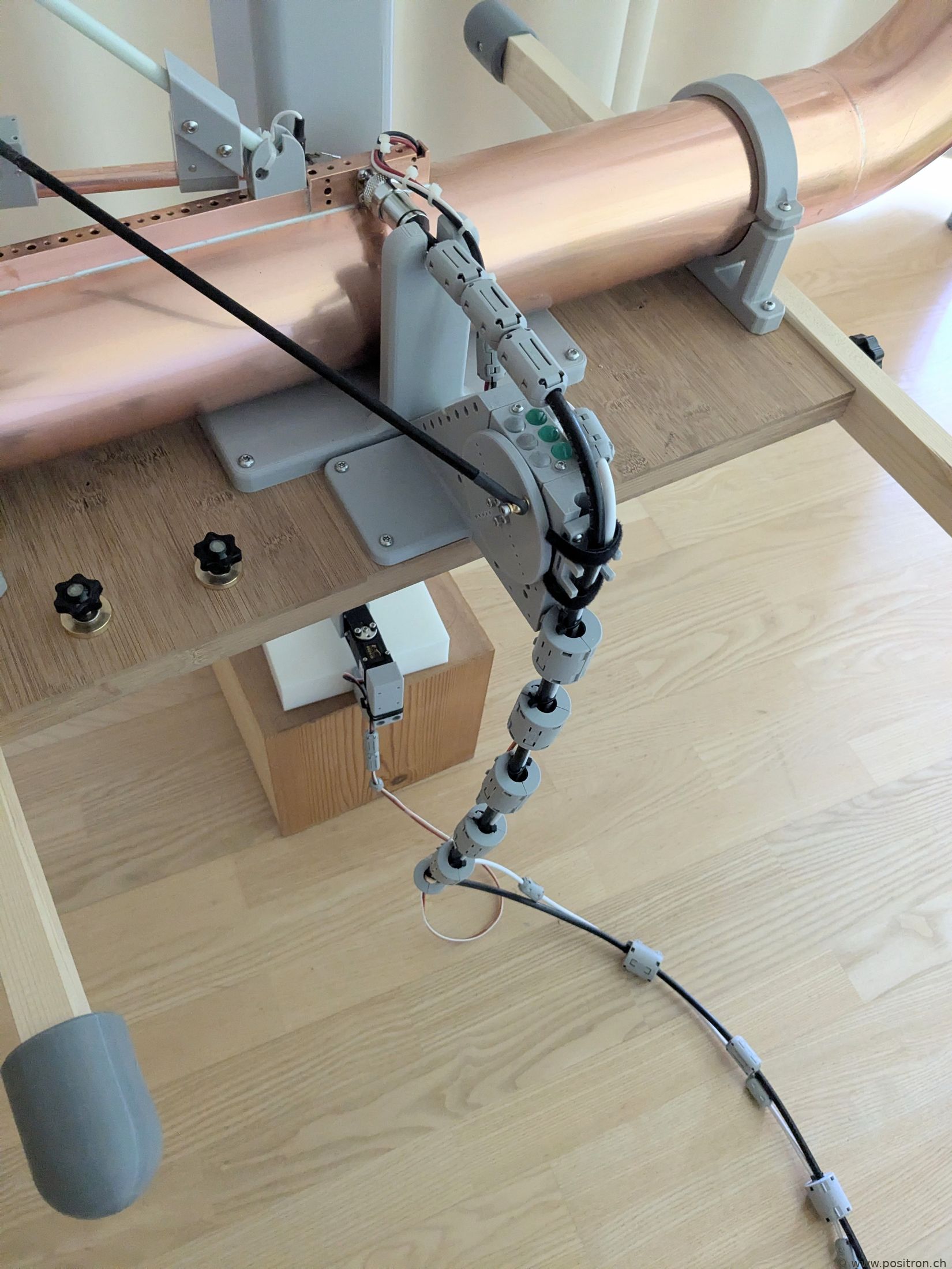
Cable entry.
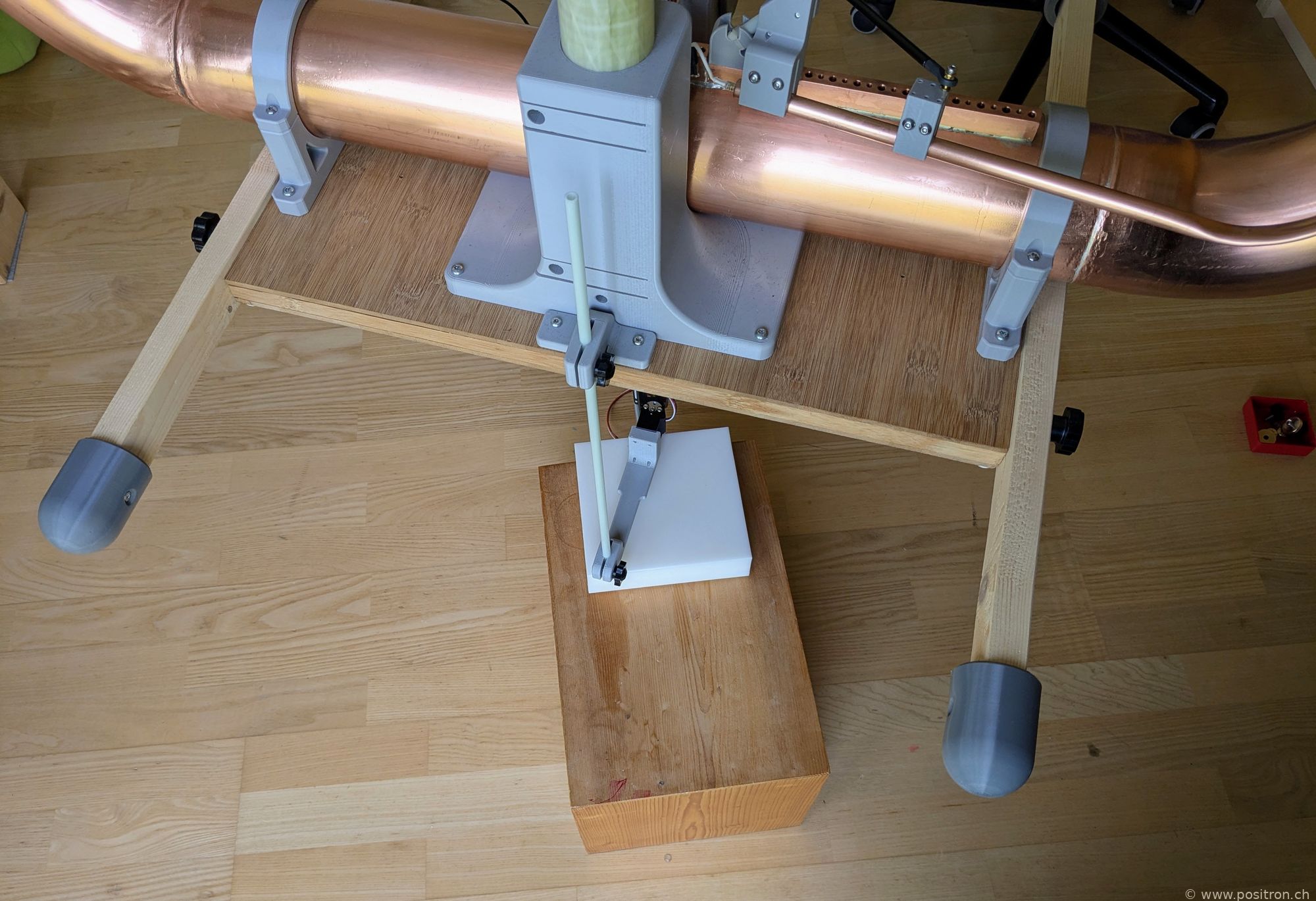
Servo for Azimuth Control
Second version: servo at the bottom which aligns the antenna azimuth.
Warning Light
The red LED is lit: keep safety distance!
Variable Capacitor Miscellaneous
3D printed hand screws for connecting the additional capacitors.
First version: a DC motor turns the variable capacitor. The capacitance is shown on a multimeter.
Link to short film (mp4)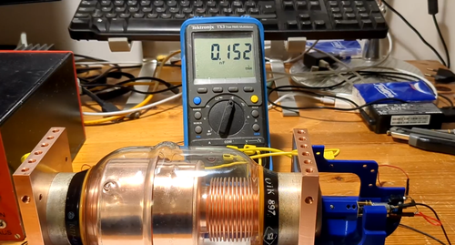
Second version: the capacitor shaft is moved by a servo.
If the shaft were screwed out too far, the flag on the shaft would catch on the plastic holder and prevent the shaft from turning.
Link to short film (mp4)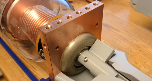
Second version: the capacitor shaft is moved by a servo.
Link to short film (mp4, no audio)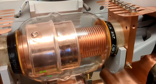
Outdoor Measurements at Distance from the House
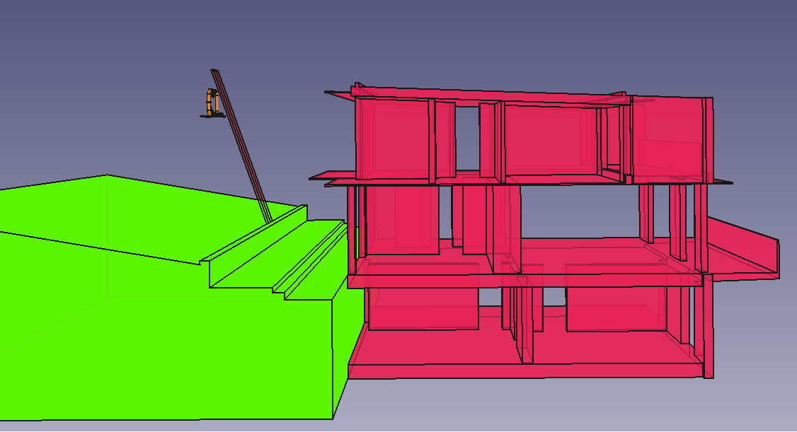
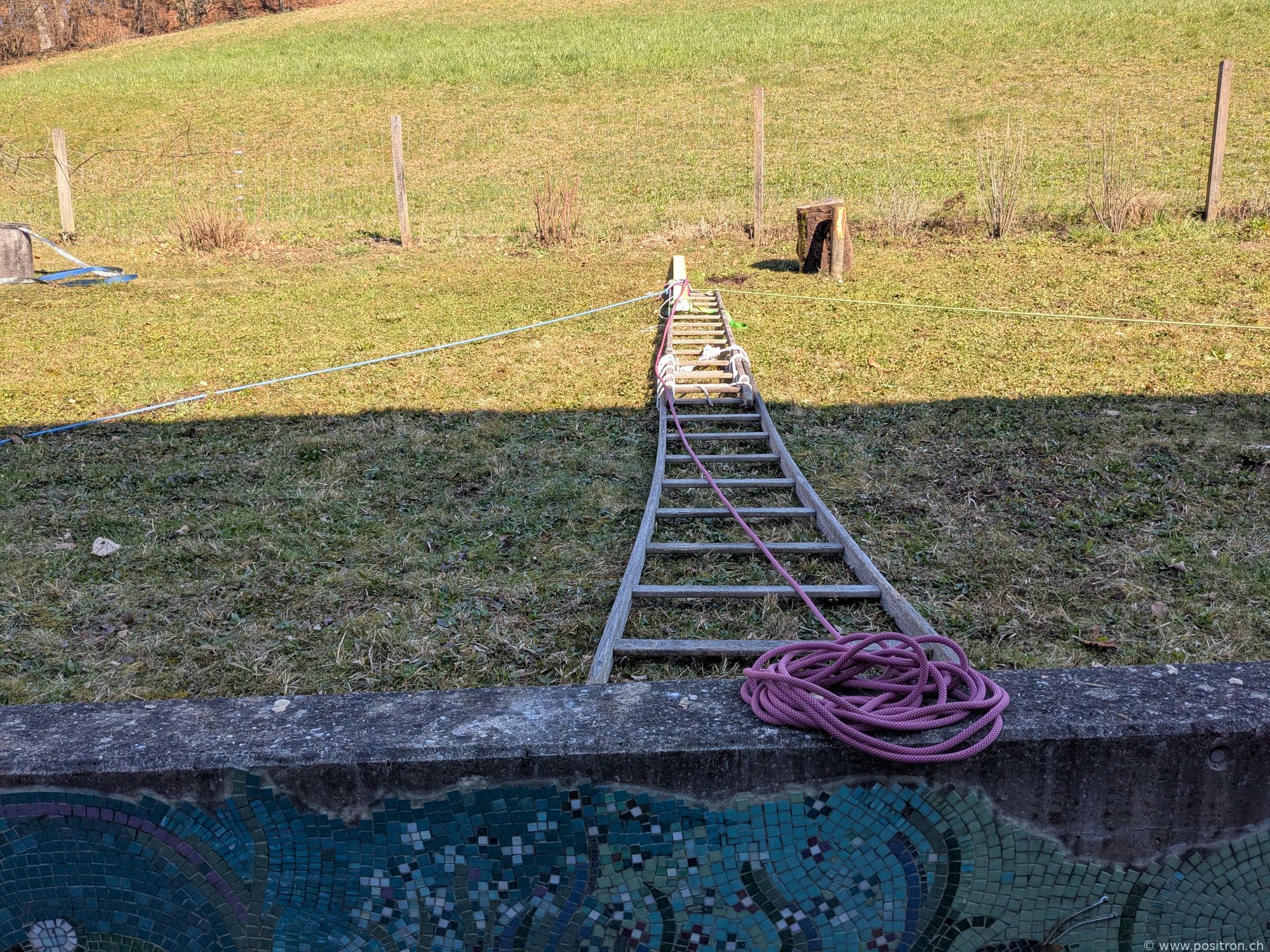
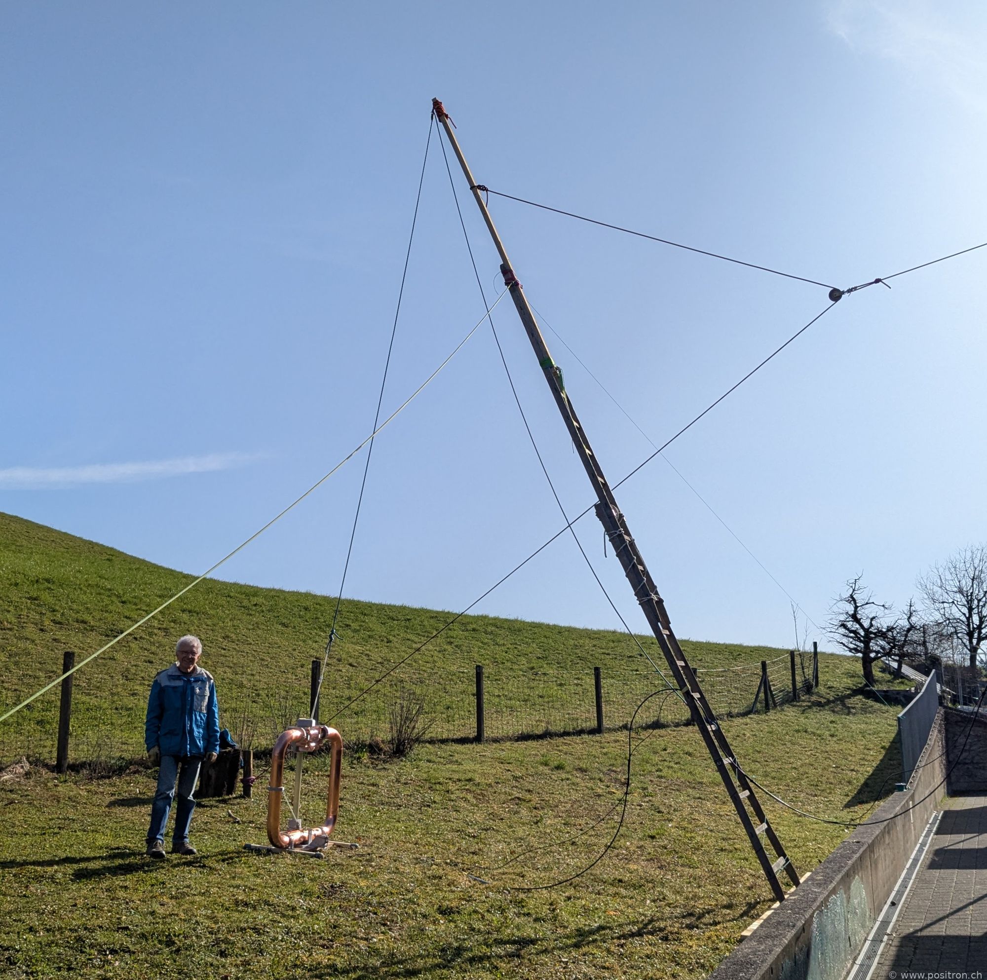
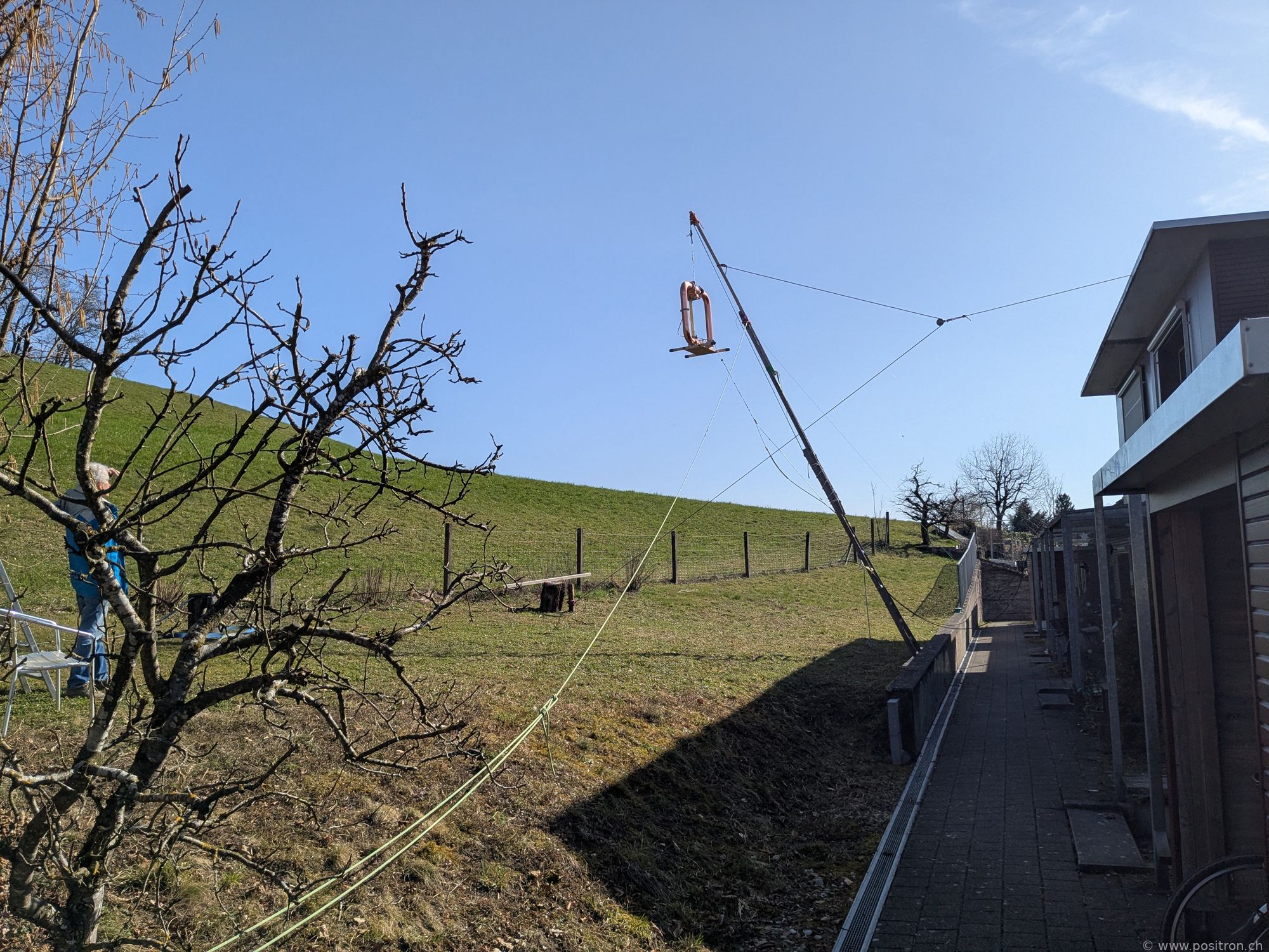
For measurements as far from the house as possible, the antenna is raised on a rope attached to a wooden ladder.
Ladder on the ground.
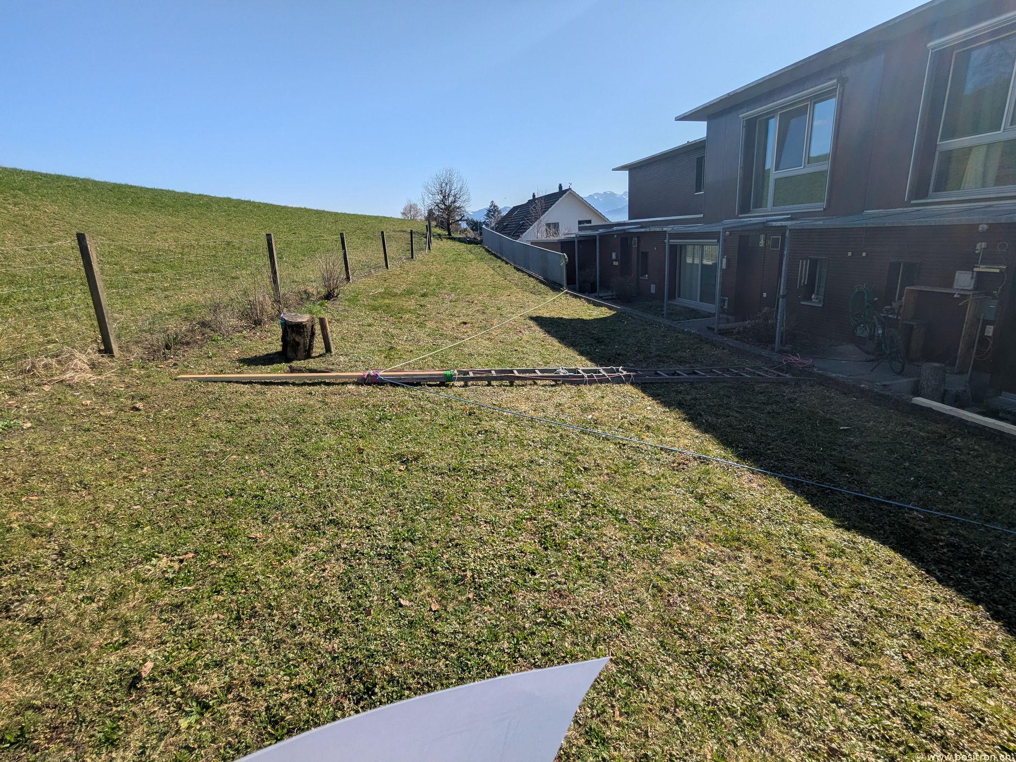
Hans attaches ropes.
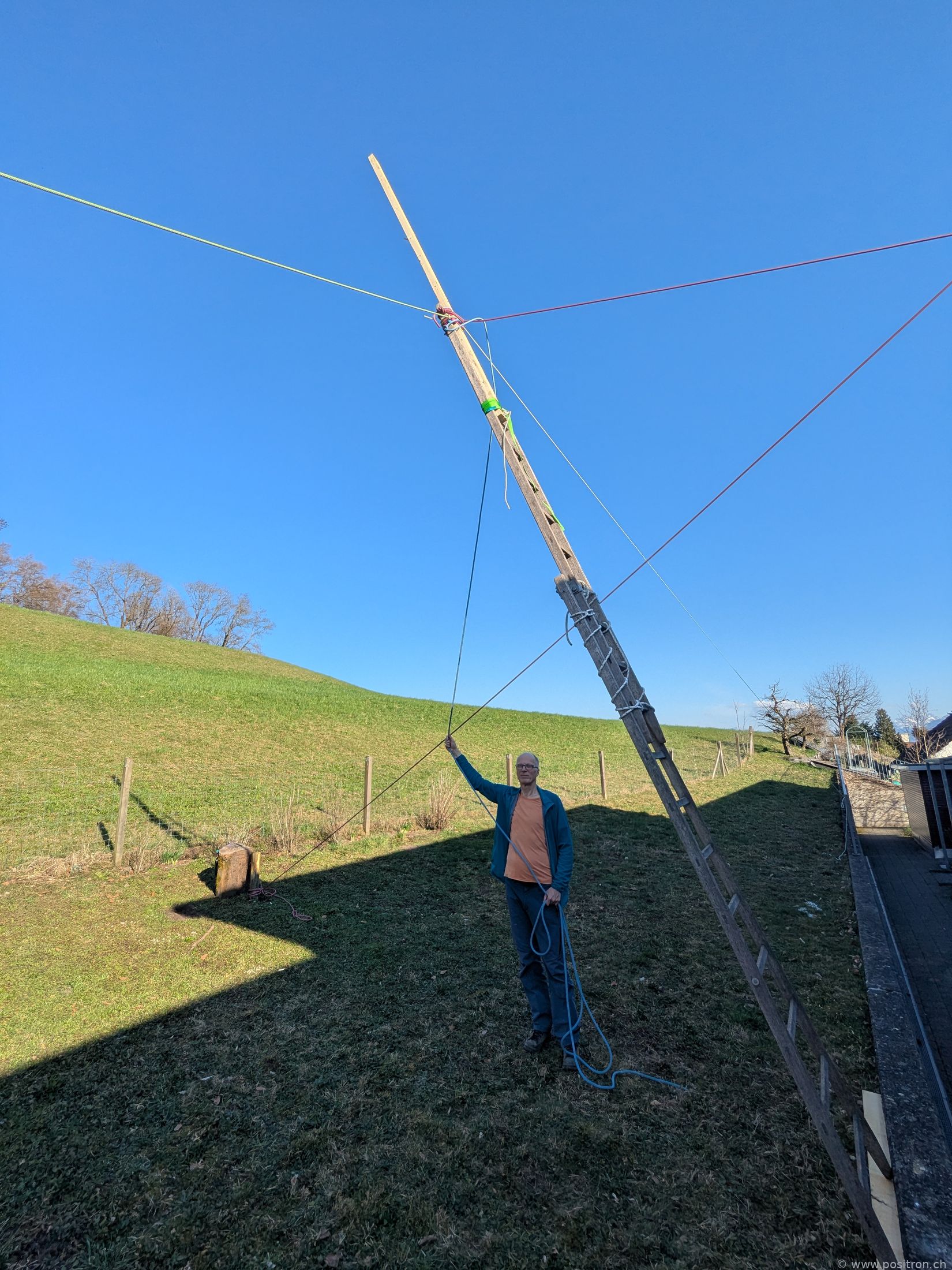
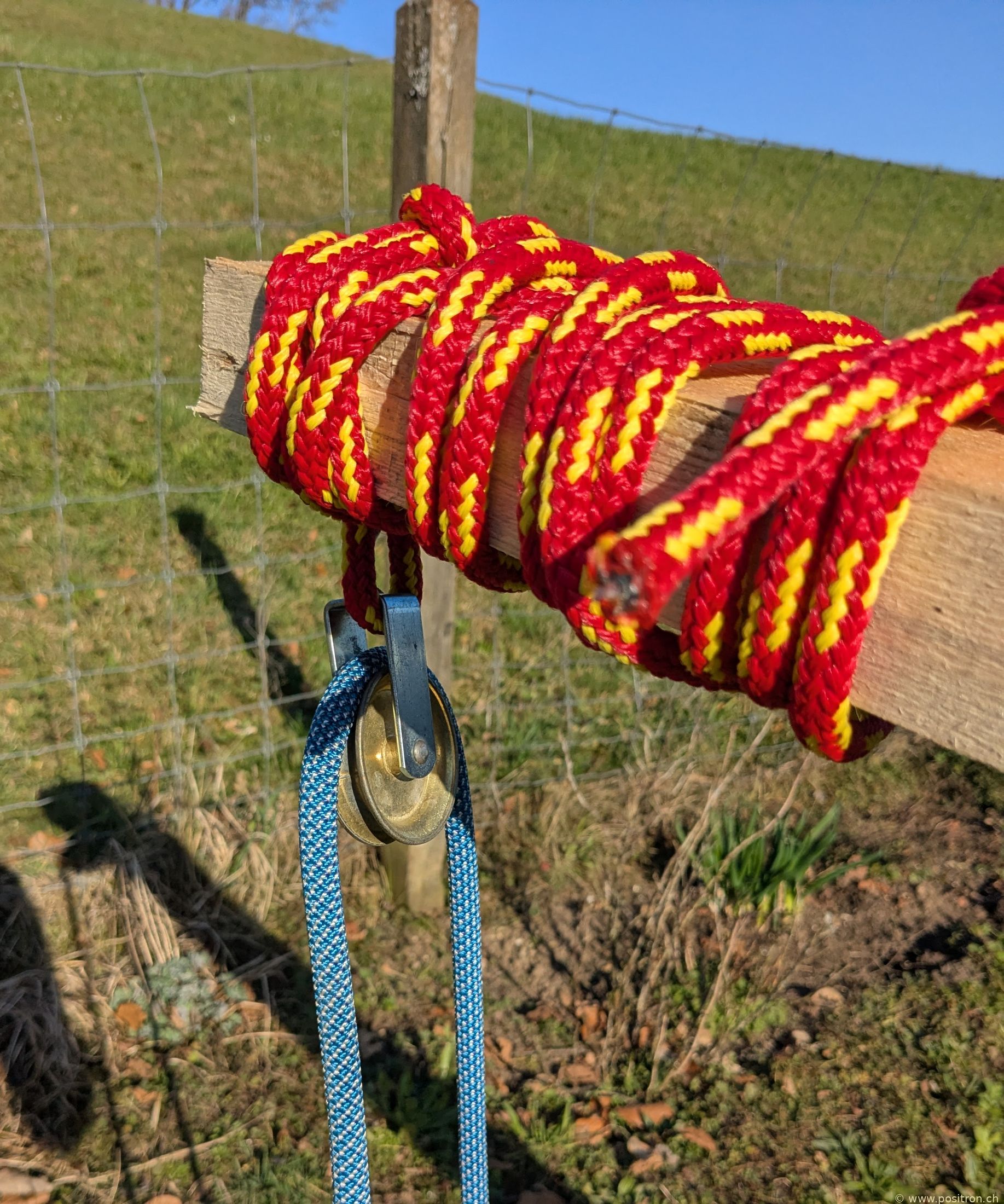
The ladder is extended with a beam. At the end there is a pulley.
Antenna attached.
Antenna raised.
The Q factor at height is so high that even at the minimum gamma match position the coupling is too strong. A temporary, smaller gamma match is formed using a banana cable.