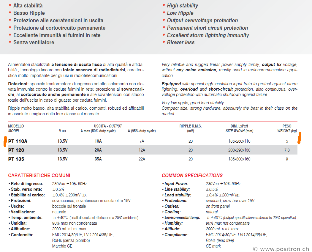
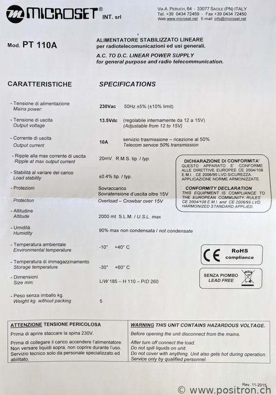
Specifications
Proper GND Connection
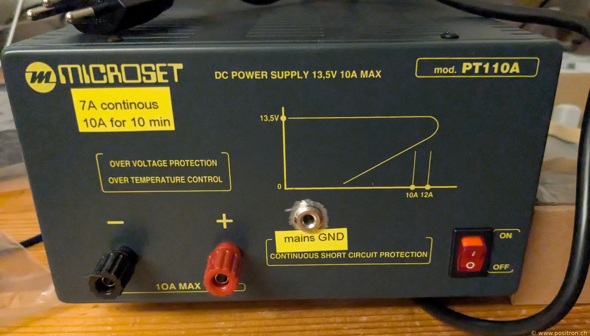
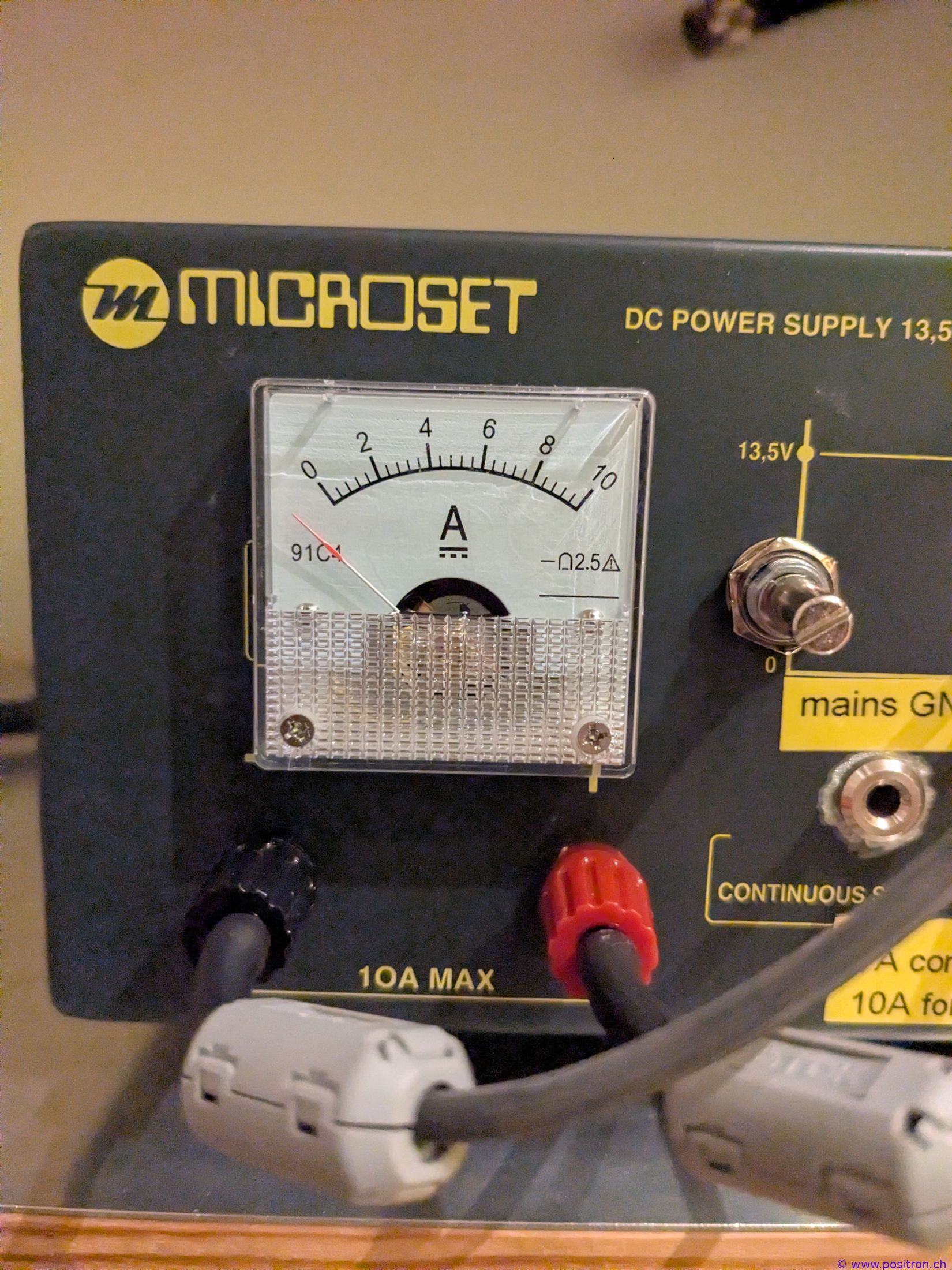
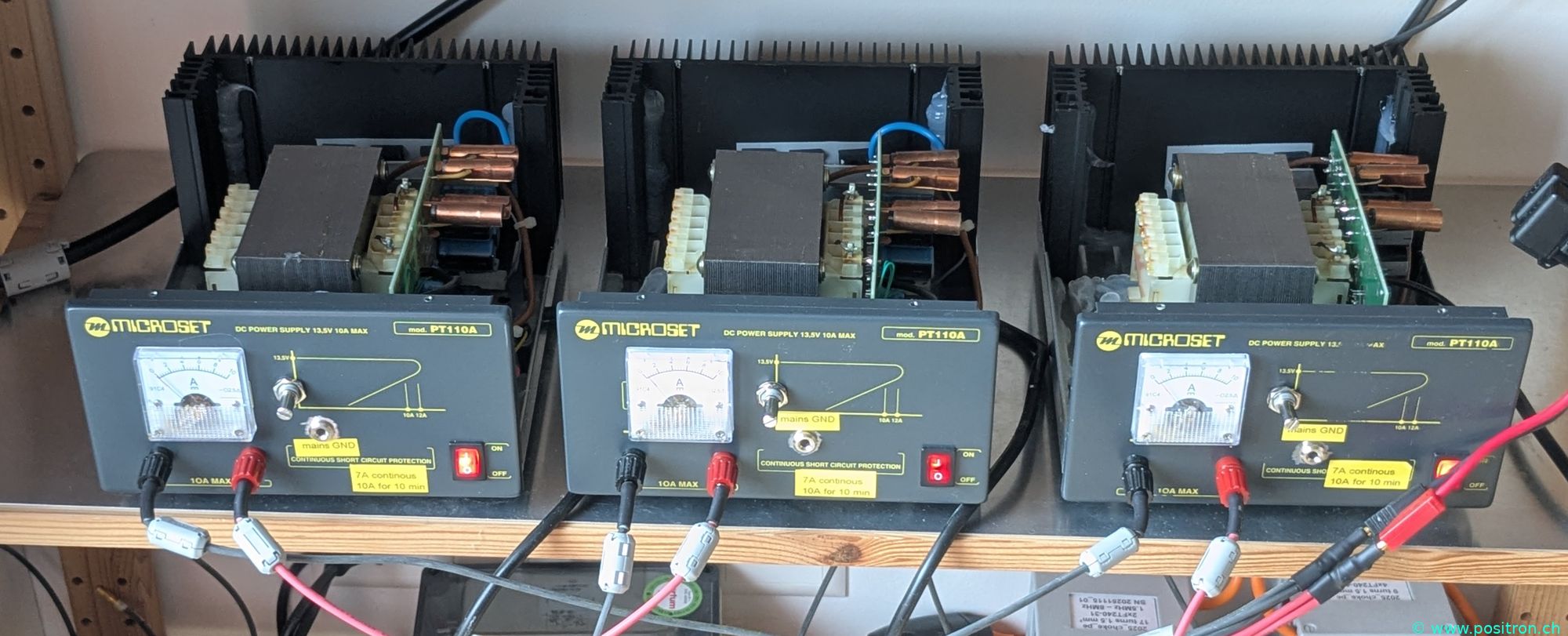
A few words about the front panel print:
The diagram with the odd curve to the right means nothing to me — I don't think it actually reflects the built-in technology. It could have been that the units behave benignly and can simply be connected in parallel. That turns out not to be the case.
It would be helpful if the manufacturer had printed the key specifications on the front panel instead of the odd diagram: 10 A at 50% on-time cycle and 7 A at 95% on-time. This information is important.
The 7 A at 95% on-time spec could reasonably be simplified to continuous. My yellow sticker label is kept accordingly brief.
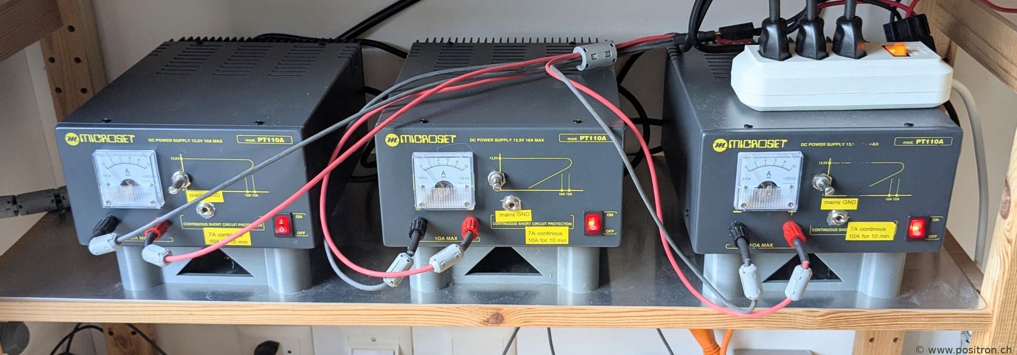
Running 3 Units in Parallel
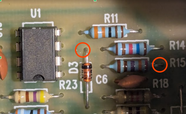
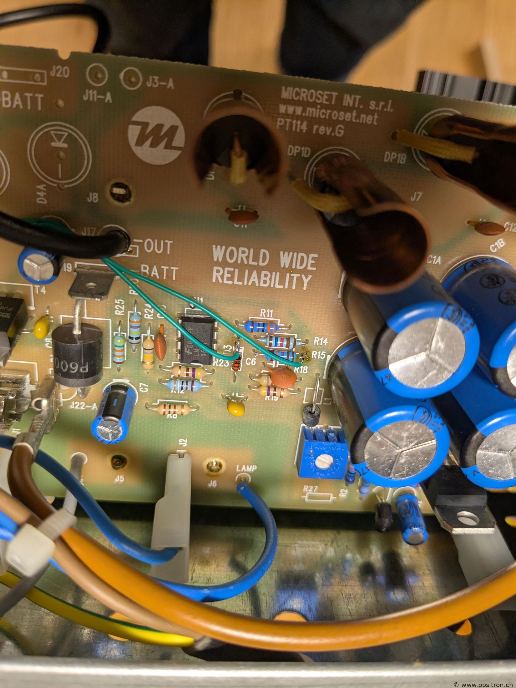
Inside, on the circuit board, there is a single-turn trimmer that sets the output voltage. The adjustment accuracy is poor, and the housing must be opened to access it.
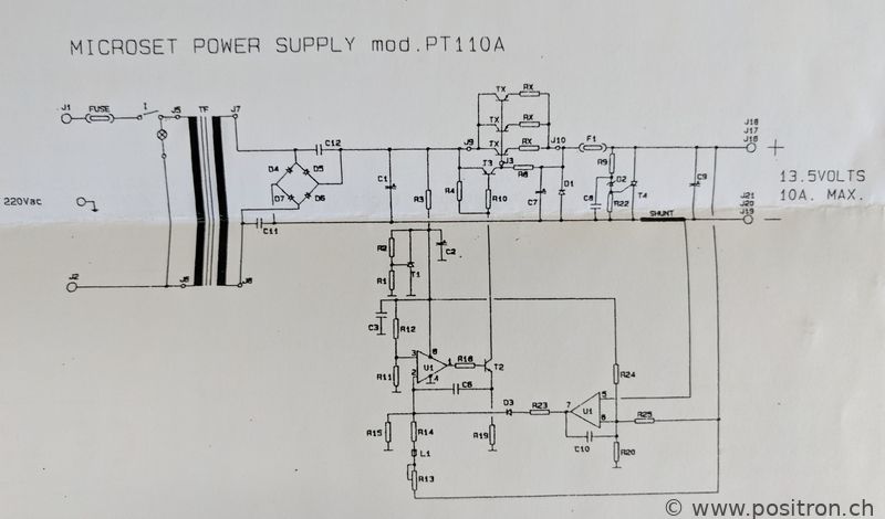
I decide to install an external trimmer so I can set the voltage more precisely.
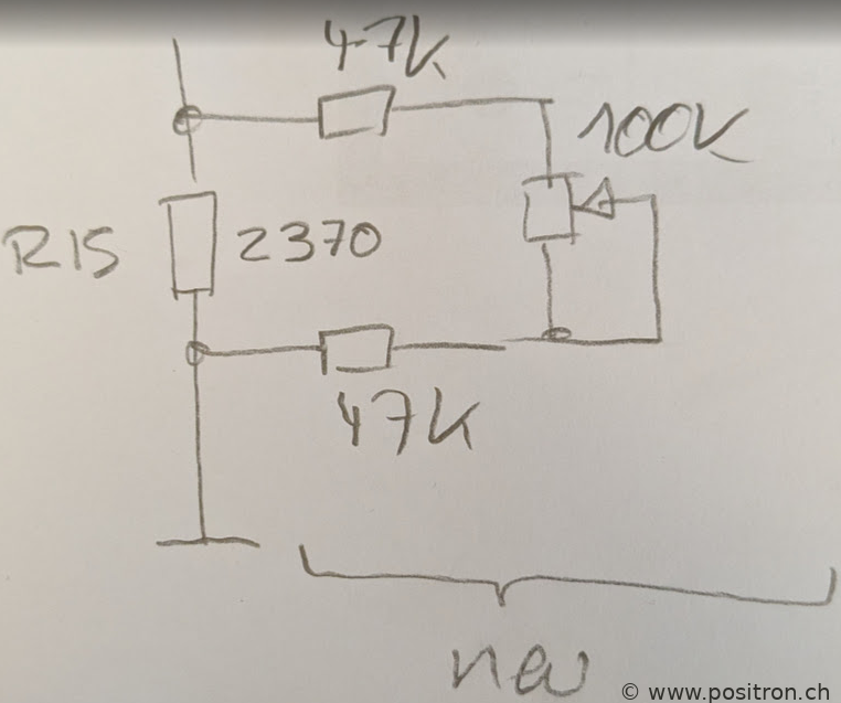
With a 10-turn trimmer of 100 kΩ I can adjust the voltage by 0.28 V. Here is the circuit diagram.
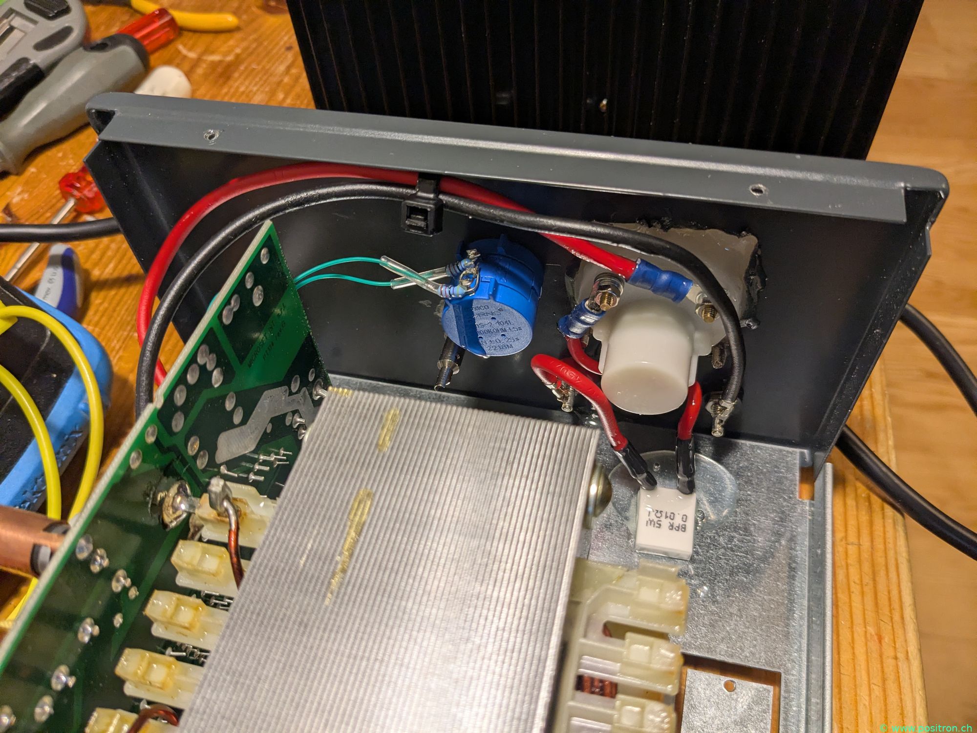
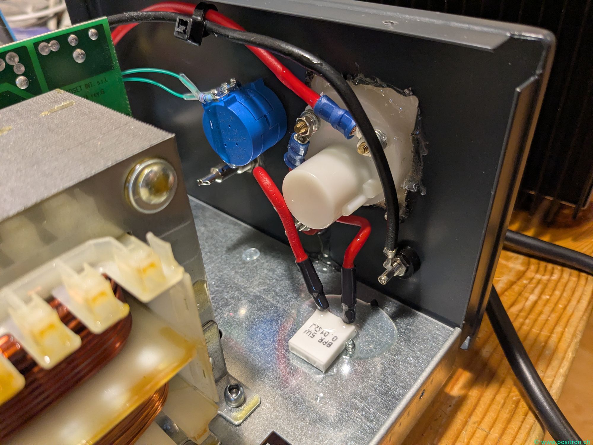
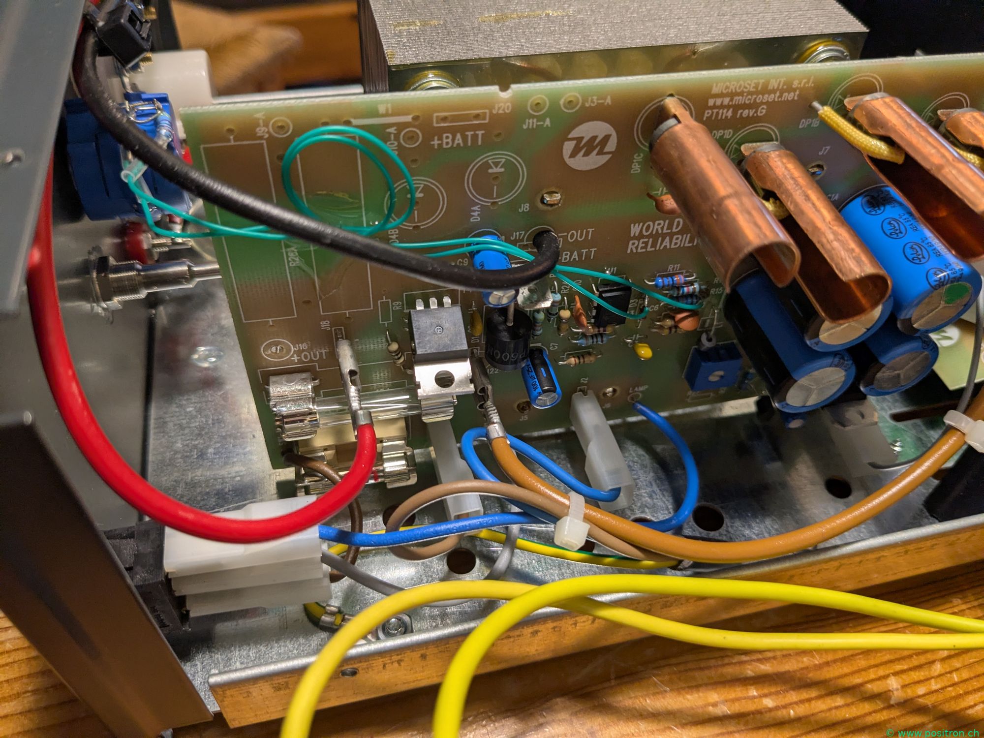
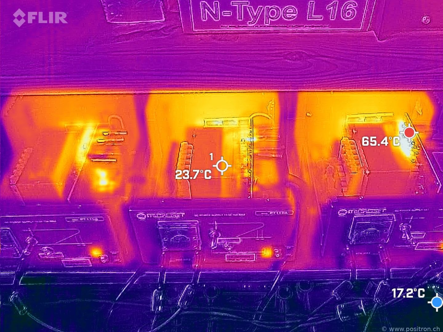
Balancing: I turn all pots on the front panel to the right stop and adjust the voltage with the internal trimmer to 13.9 V. Using the front panel pots I then reduce the voltage back to 13.8 V. The current is now evenly distributed across all three power supplies. The newly installed current meters make this easy to monitor. No cable sleeves to prevent the diode leads from touching the copper heatsink.
Problem with Faulty Rectifier Diodes
I measured the diodes with a multimeter — no anomalies found. However, something does seem to be wrong.
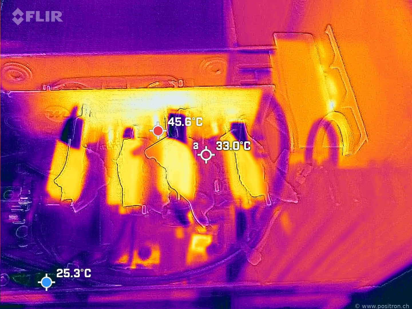
If one diode path is faulty, it causes excessive DC current through the transformer, which then starts to saturate. The current in the still-functioning path is also correspondingly higher. This together explains the loud humming.
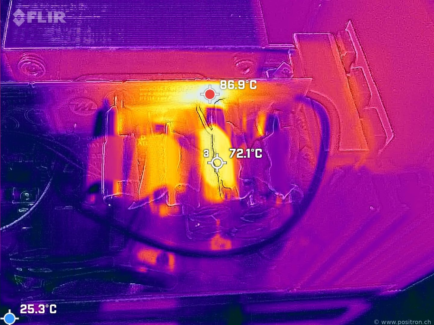
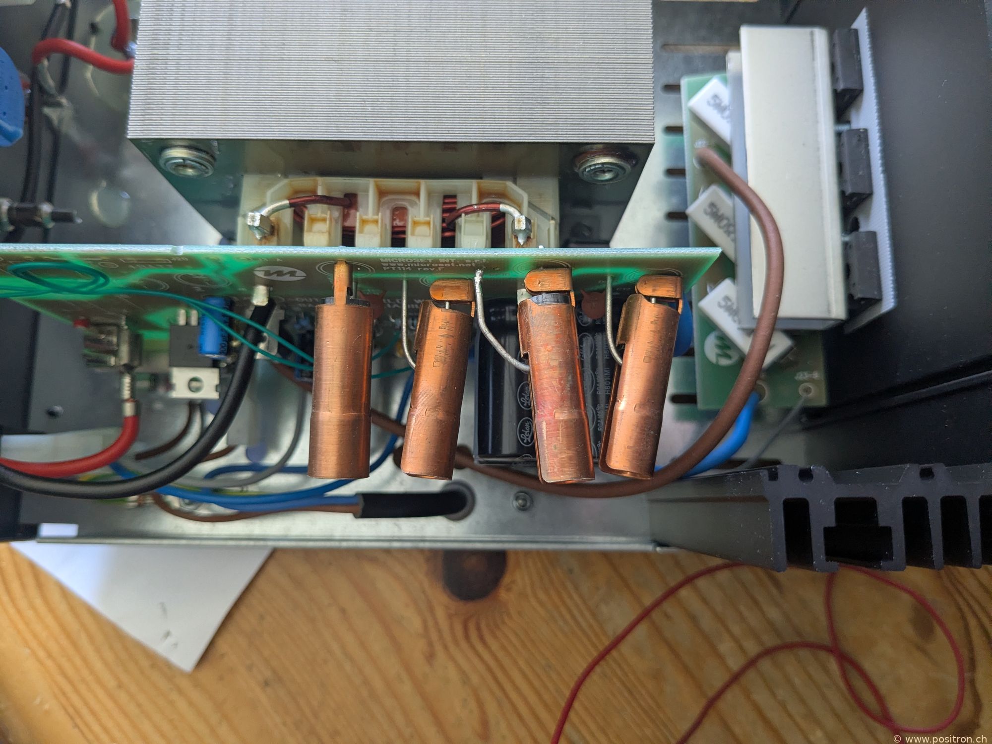
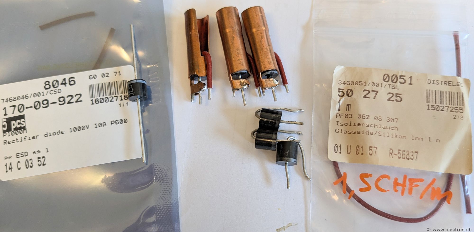
As a precaution I replace the diodes of all units with new ones of type P1000G (10 A). I also protect the lead wires with glass-silicone sleeving. These were missing on the faulty unit and may well have been the reason it failed.
I solder the cathode of the diodes directly to the heatsink. The thermal transfer should be considerably better this way.
My Opinion
My verdict on this power supply:
- The missing insulation sleeves on the diodes of one unit do not inspire confidence. (rev. F: missing sleeves, rev. G has sleeves)
- The choice of rather weak diodes is somewhat disappointing.
- The output voltage adjustment using a cheap single-turn trimmer with a wide range is poor.
- The permanently attached mains cable is impractical — I would have preferred an IEC connector socket.
- The characteristic curve printed on the front panel is very odd.
- No fan — great —nothing to break or make noise.
Whether better alternatives exist, I don't know.